
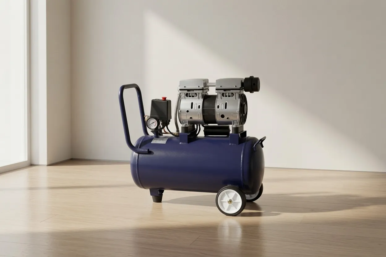
Pre-Installation Planning: What to Decide Before the Machine Arrives
The most common and expensive installation mistakes are made before the compressor is even ordered — in the planning phase. Room dimensions, ventilation opening positions, pipe route decisions, and electrical supply capacity all need to be confirmed against the compressor’s actual specifications before the machine arrives on site. Retrofitting these elements after installation invariably costs 2–5× the price of getting them right in planning.
For an oil-free air compressor installation, the following parameters must be confirmed from the manufacturer’s technical data before finalising the room or plant area design:
- → Unit footprint (L × W)
- → Total height including service access panels
- → Minimum clearances to walls and ceiling
- → Weight (for floor loading assessment)
- → Access routes for installation (door widths)
- → Maximum allowable ambient temperature
- → Heat rejection rate (kW to room)
- → Cooling air volume required (m³/min)
- → Cooling air inlet temperature max
- → Exhaust air discharge direction & velocity
- → Voltage & phase (415V 3-phase for most industrial)
- → Full load current (FLC)
- → Starting current (or VSD soft-start current)
- → Compressed air outlet size & position
- → Condensate drain outlet size & position
Before installation commences, confirm: (1) the compressor has Australian Design Registration (ADR) if it incorporates a pressure vessel above threshold; (2) the electrical installation will be carried out by a licensed electrician to AS/NZS 3000; (3) any compressed air piping will be installed per AS 4041 (pressure piping); (4) if the receiver tank exceeds statutory thresholds, it must be registered with the relevant state authority (WorkSafe Victoria, SafeWork NSW, etc.).
Compressor Room Design: Dimensions, Layout & Floor Requirements
The compressor room is not just storage — it is an engineered environment that must support the machine’s thermal, acoustic, and access requirements simultaneously. Getting the room right determines whether the compressor operates at its rated efficiency or fights against its environment from day one.
Minimum Room Clearances
| Clearance Location | Small Unit (<30 kW) | Medium Unit (30–75 kW) | Large Unit (>75 kW) | Purpose |
|---|---|---|---|---|
| Front (control panel side) | 800 mm | 1,000 mm | 1,200 mm | Operator access, panel opening clearance |
| Rear (service access) | 600 mm | 800 mm | 1,000 mm | Filter, cooler, and drive access for service |
| Sides | 500 mm | 600 mm | 800 mm | Cooling airflow pathway; avoid dead air pockets |
| Above (ceiling clearance) | 500 mm | 700 mm | 900 mm | Exhaust air discharge path; motor lift-out space |
| Between multiple units | 800 mm | 1,000 mm | 1,200 mm | Prevents hot exhaust recirculation between units |
Floor Loading & Foundation
Modern packaged oil-free rotary screw compressors are designed for direct floor mounting — no special anti-vibration pads or isolated foundations are required for units below approximately 132 kW. The factory-installed rubber isolator mounts on the skid base provide adequate vibration isolation for standard concrete slab floors.
Floor requirements: minimum 150 mm reinforced concrete slab (or equivalent structural floor rated for the machine weight with a minimum 3× dynamic factor). Verify floor loading capacity for your specific unit — a 75 kW packaged compressor typically weighs 1,200–1,800 kg. The floor must be level to within 5 mm across the compressor footprint; shimming the skid base on an unlevel floor is acceptable for small corrections but should not exceed 10 mm at any support point.
Ventilation: The Most Critical and Most Overlooked Installation Factor
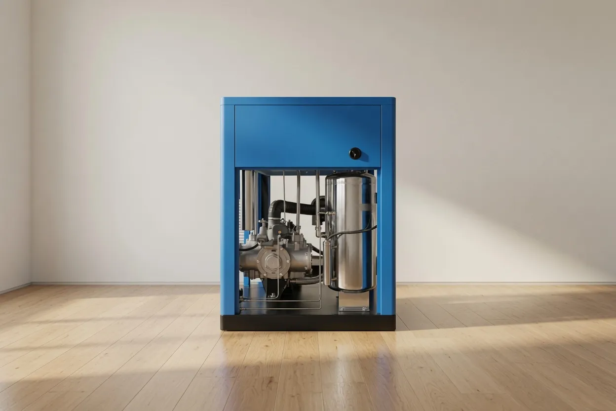
Inadequate ventilation is the single most common cause of oil-free compressor underperformance and premature failure in Australian installations. As discussed in the heat recovery article, a compressor converts 88–94% of its electrical input to heat — all of which must be removed from the compressor room continuously during operation. Failure to do so results in elevated ambient temperature, which cascades into reduced cooling efficiency, higher discharge temperatures, more frequent overtemperature shutdowns, and accelerated component wear.
The critical metric is maximum allowable compressor room temperature — typically specified as 40–45°C by most manufacturers. In Australian summer conditions, outdoor ambient temperatures regularly reach 35–42°C across much of the continent. Without active ventilation designed for these conditions, a compressor room can easily reach 50–60°C during peak summer production — well above the equipment’s rated operating limit.
Calculating Required Ventilation Air Volume
1.2 = air density × specific heat constant (kg/m³ × kJ/kg·K simplified)
ΔT = allowable temperature rise in room (°C) = max allowable room temp − max outdoor ambientExample: 45 kW compressor, heat rejection 38 kW, max room 40°C, summer ambient 35°C:
Q = 38 ÷ (1.2 × 5) = 6.3 m³/s = 380 m³/min required ventilation airflow
Ventilation System Options
An exhaust fan (or the compressor’s own cooling fan in ducted configurations) draws warm air from the compressor room through an insulated duct to atmosphere. Fresh air enters through a louvred inlet on the opposite wall at low level. This is the most reliable and controllable ventilation approach.
Large louvred openings (inlet low on one wall, outlet high on opposite or roof) allow natural convection to drive air through the room. Simple and low-maintenance, but dependent on outdoor-to-indoor temperature differential. Inadequate in hot Australian climates when ΔT is small.
Using the general building HVAC to cool the compressor area. Rarely adequate — building HVAC is not designed for the concentrated heat load of an industrial compressor, and the compressor’s dust generation from air intake can compromise HVAC filter life. Usually requires supplementary dedicated ventilation.
A common mistake in repurposed rooms or buildings without external walls. A sealed room with no fresh air inlet and no exhaust pathway causes exponential room temperature rise — the compressor heats the air, which reduces cooling efficiency, generating more heat, further raising temperature. This configuration will cause overtemperature shutdown within hours on a warm day.
Intake Air Quality: What the Compressor Breathes
The quality of air drawn into the compressor’s intake directly affects both the quality of compressed air produced and the service life of internal components. For an oil free compressor, which relies on precision mechanical clearances rather than oil film protection between moving parts, particulate contamination in intake air is particularly consequential — abrasive dust particles in intake air can accelerate rotor tip wear in dry oil-free screw units.
The compressor’s intake air filter is the first line of defence, but the filter can only remove particles down to its rated micron size — and only when it is clean. As the filter loads with dust, pressure drop across it increases, reducing volumetric efficiency and increasing the temperature of the air entering the compression element. Regular filter inspection and replacement is one of the most impactful maintenance tasks for compressor performance and component life.
- → Near welding or grinding operations
- → Near spray painting booths
- → Above vehicle exhaust areas
- → Near chemical storage or solvent use
- → In high dust loading environments (grain, mining, construction)
- → Clean, shaded, outdoor air (cooler = denser)
- → North-facing in southern Australia (shaded from afternoon sun)
- → At least 2m above ground (cleaner, cooler air)
- → Fitted with weather louvre to exclude rain
- → At least 3m from any exhaust or hot air discharge
- → Pressure drop indicator (red zone = replace)
- → Time-based: every 1,000–2,000 hrs (dusty env: 500 hrs)
- → Visual inspection monthly in high-dust environments
- → Discharge temperature rise of >5°C above baseline may indicate filter restriction
Compressed Air Pipework: From Compressor to Distribution Header
The compressed air pipe system between the compressor outlet and the facility distribution header is the critical link between the machine’s rated output and the pressure actually available at the tools and processes. Every component in this run — flexible connections, isolation valves, dryers, filters, and the receiver tank — introduces pressure drop. Managing the sum of these drops is the fundamental objective of pipework design for an oil-free compressed air system.
Equipment Sequence: Compressor to Distribution
Outlet
Connection
Valve
Receiver
Coalescer
Dryer
+ Carbon
Header
Flexible Connection: Why It Matters
The first element after the compressor outlet must be a flexible connector — a braided stainless or high-pressure rubber hose rated for the system pressure. This serves two critical functions: it isolates vibration from the compressor body (preventing pipe fatigue fractures at rigid connections) and accommodates thermal expansion of the compressor body during warm-up without stressing the pipe joint. Rigid pipe connected directly to the compressor outlet is a common installation error that causes joint failures within 1–3 years due to vibration fatigue.
Flexible connector length: minimum 300 mm for units below 45 kW, 500 mm for larger units. Rated pressure minimum 1.5× system maximum pressure. Replace at 5-year intervals regardless of condition — the braided reinforcement fatigues internally before external signs appear.
Electrical Installation: Supply, Protection & VSD Considerations
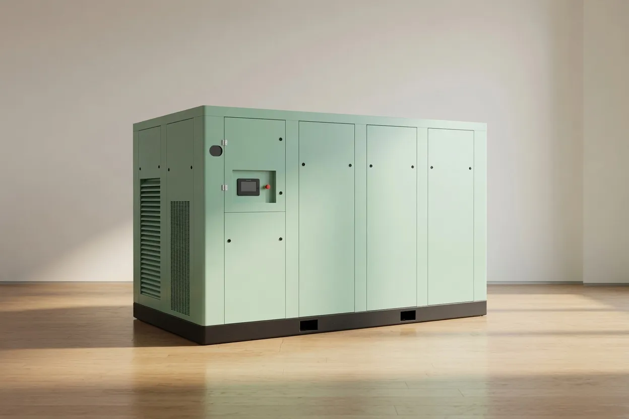
Electrical installation for an oil-free rotary screw compressor above 5 kW must be carried out by a licensed electrician to AS/NZS 3000. The following parameters require particular attention:
Size supply cable for 125% of full load current (FLC) to the motor nameplate. Voltage drop from the main switchboard to the compressor must not exceed 3% at FLC — excessive voltage drop causes reduced motor torque, higher slip, elevated winding temperature, and efficiency reduction. For VSD units, cable capacitance must be considered — long cable runs between VSD output and motor may require output chokes to suppress capacitive discharge currents that damage motor winding insulation.
Motor protection relay (MPR) or electronic overload relay set to 100–105% of full load current provides overtemperature protection. For VSD-equipped compressors, the VSD typically provides integrated motor protection — confirm with the manufacturer whether an additional external MPR is required. Circuit breaker or fuse sizing should match the VSD’s recommended upstream protection specifications, not generic motor starting rules.
Variable speed drives generate high-frequency switching harmonics that require careful earthing. The VSD cabinet must be earthed with a dedicated low-impedance conductor (not shared earth with other equipment). Screened motor cable (with screen earthed at both ends) is required for VSD-to-motor runs above 10 metres to comply with EMC requirements under AS/NZS CISPR 11 for industrial environments. Failure to screen results in interference with nearby instrumentation and control equipment.
VSD compressors draw non-sinusoidal current from the supply, generating harmonic distortion that can affect other equipment on the same electrical system. For facilities with sensitive instruments, medical equipment, or multiple large VSDs, a power quality assessment should be conducted and line reactors or active harmonic filters specified if voltage distortion exceeds AS 61000 limits for the supply point.
Commissioning Checklist: Getting It Right the First Time
A structured commissioning process confirms that every element of the installation is correct before the machine enters production service. Skipping or rushing this step leads to premature component wear, inaccurate performance baseline records, and potential safety issues with a pressurised system.
Installation Support from Australia Oil Free Air Compressor
Australia Oil Free Air Compressor Co., Ltd. provides installation design support as part of every compressor proposal for units above 15 kW. Our engineering team at the Charlton Industrial Area facility reviews proposed room layouts, ventilation design, and pipework routes before confirming equipment specifications — not after the concrete is poured.
We supply installation datasheets, ventilation calculation worksheets, and commissioning checklists for every unit we sell. Our service network includes certified technicians across major Australian cities for on-site commissioning support. For large installations, we provide written commissioning reports with baseline operating data that become the reference document for all future scheduled maintenance.
Contact us at [email protected] with your proposed installation layout for a review before committing to construction.
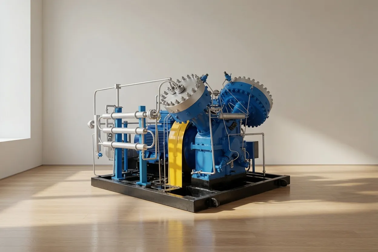
CM242GPV — Medium-Pressure Oil-Free Screw Air Compressor
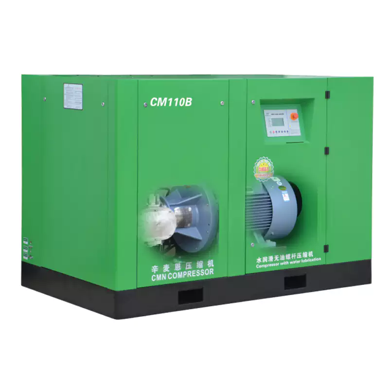
The CM242GPV is designed with installation practicality in mind — a compact footprint relative to output rating, defined cooling air inlet and exhaust positions for straightforward ducted ventilation, and a single-point compressed air outlet with 360° connection flexibility. For facilities building or retrofitting a dedicated compressor room, the CM242GPV’s well-documented installation requirements make planning straightforward. Full installation datasheets, ventilation airflow data, and commissioning checklists are provided with every unit.
Frequently Asked Questions
Australia Oil Free Air Compressor Co., Ltd.
Charlton Industrial Area, Australia | [email protected]