Description
Engineering Natural Gas Compression at Pipeline Scale
Natural gas — predominantly methane (CH4) — has become the backbone fuel of modern industrial economies, powering everything from combined-cycle power plants to city heating grids and petrochemical feedstock pipelines. Moving this gas reliably across vast distribution networks, from marginal wellheads to urban demand centres, demands compression technology built to an entirely different standard than general-purpose industrial air compressor platforms. Pipeline gas is not a clean, dry, single-component stream. Raw and gathered gas carries trace moisture, higher-chain hydrocarbons, and sometimes corrosive hydrogen sulfide. It arrives at compressor intakes at wildly fluctuating pressures as wells age and grid demand shifts throughout the day.
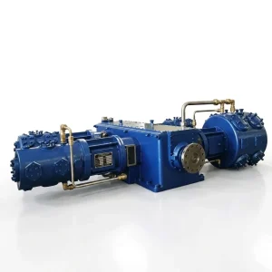
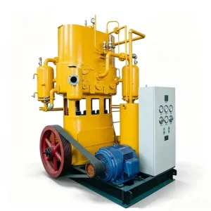
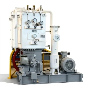
Our Medium and Low Pressure Natural Gas Compressors address every one of these variables. Engineered in close alignment with API 618 design philosophies for petroleum-service reciprocating machinery, these units range from compact 20 m³/min LW-series skids to 600 m³/min, 30-tonne four-row synchronous powerhouses — each built with hermetic sealing systems that prevent a single cubic centimetre of methane from reaching the atmosphere.
Zero Fugitive Emissions
Nitrogen-purged distance piece architecture routes every trace of methane blowby directly to the flare header. Zero atmospheric CH4 leakage under any operating condition.
Wet Gas Tolerance
Large-bore cylinders with low-lift aerodynamic valves handle liquid hydrocarbon dropouts that destroy centrifugal and rotary screw alternatives through blade erosion and liquid hammer.
VFD-Ready Flexibility
Seamless 50–100% capacity turndown via variable frequency drives and automated cylinder unloaders — matching real-time pipeline demand without wasteful bypass energy losses.
Three Core Engineering Systems That Define Pipeline-Grade Performance
Handling hundreds of cubic metres of explosive gas per minute requires purpose-built solutions for three engineering challenges that generic industrial compressors simply cannot resolve.

Complete Model Range and Technical Specifications
Our natural gas compressor matrix covers every pipeline scenario — from compact wellhead skids to mega-scale baseload station powerhouses. The table below provides a full engineering reference across all standard pressure classes.
Low Pressure Class — 0.10 to 0.25 MPa (Pipeline Gathering / BOG Recovery)
| Model | Configuration | Capacity (m³/min) | Pressure (MPa) | Power (kW) | Weight (t) |
|---|---|---|---|---|---|
| LW-20/2 | 2-row 1-stage | 20 | 0.20 | 75 | 1.80 |
| DW-290/2 | 2-row 1-stage | 290 | 0.20 | 1,000 | 17.00 |
| DW-325/2 | 2-row 1-stage | 325 | 0.20 | 1,100 | 18.00 |
| DW-300/1 | 2-row 1-stage | 300 | 0.10 | 550 | 14.00 |
| HW-600/1 | 4-row 1-stage | 600 | 0.10 | 1,100 | 30.00 |
| HW-380/2.5 | 4-row 1-stage | 380 | 0.25 | 1,300 | 28.00 |
Medium Pressure Class — 0.40 to 0.80 MPa (Gas Gathering / Distribution)
| Model | Configuration | Capacity (m³/min) | Pressure (MPa) | Power (kW) | Weight (t) |
|---|---|---|---|---|---|
| LW-30/4 | 2-row 2-stage | 30 | 0.40 | 132 | 3.40 |
| DW-120/4 | 2-row 2-stage | 120 | 0.40 | 550 | 13.00 |
| DW-150/4 | 2-row 2-stage | 150 | 0.40 | 710 | 18.00 |
| DW-100/6 | 2-row 2-stage | 100 | 0.60 | 550 | 13.00 |
| 4MW-240/6.5 | 4-row 2-stage | 240 | 0.65 | 1,300 | 26.00 |
| LW-20/8 | 2-row 2-stage | 20 | 0.80 | 132 | 3.00 |
High End — 2.50 to 5.00 MPa (Gas Turbine Fuel Boosting)
| Model | Capacity (m³/min) | Pressure (MPa) | Power (kW) |
|---|---|---|---|
| LW-60/2.5 | 60 | 2.50 | 200 |
| LW-50/5 | 50 | 5.00 | 240–250 |
Custom configurations from 11 kW to 2,000 kW available. Contact our team with your site conditions for a bespoke specification.
Pipeline Applications Across the Natural Gas Value Chain
From the extraction wellhead to the municipal distribution ring and ultimately the gas turbine combustion chamber, our compressors function as the indispensable pressure links that keep the global natural gas supply chain moving.
Gas Turbine Fuel Gas Boosting
Combined-cycle power plants require natural gas at precise turbine inlet pressures (typically 2.5 to 5.0 MPa). If the municipal pipeline pressure drops below this threshold, the turbine trips. Our LW-60/2.5 and LW-50/5 models act as dedicated fuel gas boosters, using VFDs to adapt instantly to grid pressure fluctuations and keep the power plant running without interruption.
Wellhead Gas Gathering
As gas wells age, their natural expulsion pressure declines steadily over years of production. Our high-volume DW and HW series draw remaining low-pressure gas from ageing wellheads and boost it to 0.40–0.60 MPa for regional pipeline injection. The robust piston architecture tolerates wet gas with liquid dropouts that would rapidly destroy centrifugal blower alternatives.
LNG Boil-Off Gas (BOG) Recovery
Heat ingress into LNG storage tanks causes a fraction of cryogenic liquid to evaporate as low-pressure methane. Without recovery, this BOG is flared — destroying saleable product and generating avoidable emissions. Our compressors capture this near-atmospheric-pressure gas and boost it back to pipeline injection pressure (typically 0.80 MPa), converting what was atmospheric waste into direct grid revenue.
Municipal Distribution Grid Reinforcement
Urban gas distribution networks experience peak-demand pressure drops during cold weather events. City utility operators use our mid-range DW and LW series as grid reinforcement boosters at strategic node points, automatically ramping output via VFD as residential and industrial demand peaks — preventing low-pressure events and maintaining uninterrupted supply to all connected users.
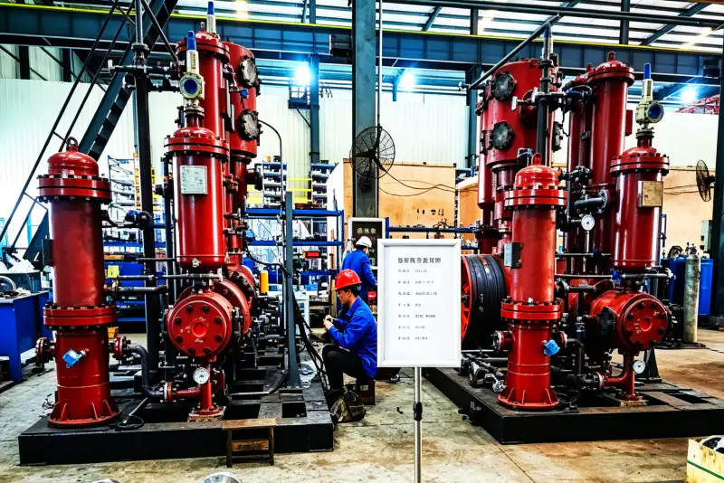
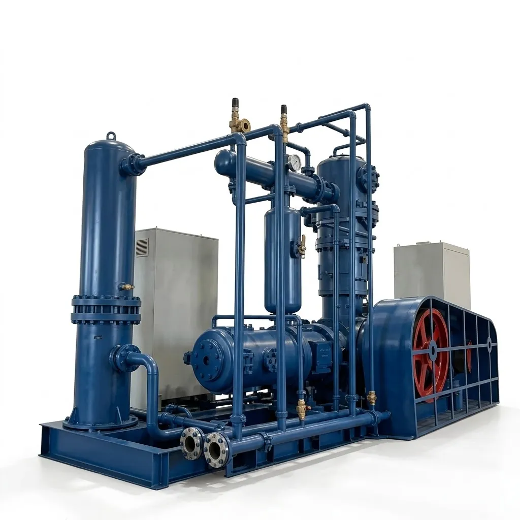
Featured Case Study: Mega-Scale Municipal Gas Gathering Station
Key Takeaway: The fundamental reason centrifugal technology failed in this application — liquid hydrocarbon impingement on high-speed rotating components — is structurally impossible in a reciprocating piston design. The large cylinder clearances and robust valve geometry that make our machines thermodynamically less elegant at fixed design points are precisely the characteristics that keep them running when real-world gas quality varies.
Installation Standards and Preventative Maintenance Protocol
A compressor station drawing over 1,000 kW and handling explosive gas in a hazardous area classification demands a disciplined engineering lifecycle — from civil foundation design through IoT-enabled remote diagnostics.
1
Civil Engineering and Hazardous Area Zoning
Units weighing up to 30 tonnes require isolated reinforced concrete foundations sized to absorb low-frequency harmonics. The installation zone must be rigorously classified per ATEX Zone 1 or Class 1 Division 1 standards. All onboard instrumentation, junction boxes, motors, and electrical enclosures require full Exd certification. A dedicated nitrogen purge manifold must be integrated to the distance piece and cylinder heads for safe pre-startup gas purging and maintenance isolation.
2
Daily Operations and Liquid Knockout Management
Automated liquid knockout drums upstream of each compressor must be confirmed operational before every shift. Liquid slugs from wet wellhead or pipeline gas are the primary cause of sudden cylinder valve failure. Drum level monitoring, with automatic dump valve actuation, keeps any condensed hydrocarbons from entering the compression cylinders regardless of upstream gas condition variations or temperature swings.
3
8,000-Hour Scheduled Overhaul
Replacement of PTFE piston rings, rider bands, and the critical distance-piece mechanical packing at 8,000-hour intervals restores volumetric efficiency and maintains the zero-leakage environmental standard. Our global parts inventory holds dedicated wear items for all models, dispatched for planned maintenance windows to minimise station downtime.
4
Remote IoT Diagnostic Telemetry
Our advanced PLC architectures support remote IoT telemetry integration. Main bearing vibration signatures, interstage gas temperatures, and lubrication oil pressures can be monitored continuously from our engineering headquarters. This predictive approach allows field service dispatch before minor wear patterns develop into unplanned shutdowns — converting reactive maintenance into a scheduled, controllable cost.
Reciprocating vs Centrifugal vs Rotary Screw — Total Cost of Ownership
When selecting compression technology for natural gas service at 0.10–5.00 MPa, the choice between reciprocating, centrifugal, and rotary screw platforms has long-term cost implications that go far beyond the equipment purchase price.
| Performance Metric | Our Reciprocating Natural Gas Compressors | Centrifugal / Rotary Screw Alternatives |
|---|---|---|
| Wet Gas Tolerance | ✔ Large-bore cylinders absorb minor liquid dropouts without component damage. | ✘ High-speed impellers and tight screw clearances destroyed by liquid hammer. |
| Turndown Flexibility | ✔ VFDs plus unloader valves achieve 50–100% range with zero surge risk. | ✘ Centrifugals surge dangerously below minimum flow. Bypass loops waste energy. |
| Variable Inlet Pressure | ✔ Positive displacement maintains stable discharge across declining wellhead pressures. | ✘ Aerodynamic efficiency collapses when inlet pressure deviates from design point. |
| Fugitive Emission Control | ✔ Nitrogen-purged distance piece routes all blowby to flare. Verifiable zero emissions. | ✘ Shaft seal leakage is a structural characteristic of dynamic compression machines. |
Why Pipeline Operators Choose Australia Oil Free Air Compressor Co., Ltd.
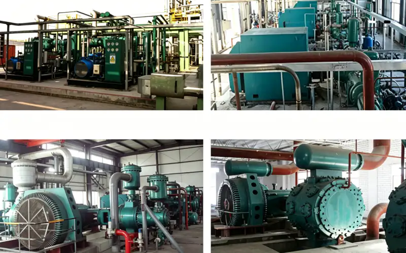
Pushing millions of cubic metres of explosive natural gas through national infrastructure daily demands a manufacturer whose quality assurance is not a marketing statement but a verifiable engineering process. Our production facilities operate under an elite ISO-certified framework with API 618 alignment throughout design, manufacturing, and factory acceptance testing.
✅
API 618 Design Philosophy
Reciprocating compressors for petroleum service designed to API standards — the benchmark specification for pipeline and process industry procurement.
✅
NDT and Hydrostatic Testing
Every cylinder block and pressure manifold undergoes ultrasonic non-destructive testing plus hydrostatic pressure trials before leaving our facility.
✅
NACE MR0175 Material Options
Sour gas applications can be fully specified in NACE-compliant alloys, eliminating H2S-induced sulfide stress cracking across the full service life.
✅
Custom Engineering up to 2,000 kW
Bespoke single-machine configurations from 11 kW compact skids to 2,000 kW mega-station powerhouses engineered to exact site specifications.
Strategic Selection Pathway for Your Application
Three sequential decisions narrow the specification to the correct model for any natural gas compression project. Working through these with our engineering team before ordering eliminates costly resizing after delivery.
Assess Your Throughput Requirement (m³/min)
A single wellhead skid may need only 20 m³/min (LW-20/2). A primary municipal gathering station handling multiple field inputs may need the 600 m³/min HW-600/1. Undersizing starves downstream users; oversizing wastes capital on unused machine scale and runs the compressor inefficiently at low load fractions.
Verify Your Target Discharge Pressure (MPa)
Simple gathering lines may target only 0.40 MPa (DW-150/4 range). Gas turbine fuel supply typically demands 2.50 to 5.00 MPa (LW-60/2.5 or LW-50/5). Confirm your target from the gas turbine or pipeline licensor specification before entering the model selection table — pressure class determines staging architecture entirely.
Confirm Electrical Infrastructure Capacity
Driving a 1,300 kW motor (4MW-240/6.5) or a 1,100 kW machine (HW-600/1) requires 6 kV or 10 kV medium-voltage switchgear and a substation capable of handling startup inrush currents. Existing 380 V infrastructure limits selection to the LW series compact units. Electrical infrastructure confirmation prevents a very expensive post-order surprise.
Build a Zero-Emission Natural Gas Compression Station
Contact the engineering team at Australia Oil Free Air Compressor Co., Ltd. with your site flow rates, inlet conditions, and discharge pressure targets. We will return a fully specified model recommendation within 48 hours.
Charlton Industrial Area, Australia | [email protected]
Related Reading
For operations where energy costs are a key concern in long-running pipeline stations, this guide explains the methods in detail: oil free air compressor energy efficiency — how to cut running costs.