Description
Why Nitrogen Bottling at 150–165 Bar Demands a Dedicated Oil-Free Design
Industrial nitrogen produced by PSA (Pressure Swing Adsorption) generators or cryogenic air separation units arrives as a highly refined, premium-purity product — often 99.999% pure. To become a practical industrial utility, it must be compressed to cylinder-filling pressures of 150 to 165 Bar (15.0 to 16.5 MPa) for storage and distribution. This is where the chemistry of nitrogen and the mechanics of compression intersect in a critical way. Unlike oxygen, nitrogen will not react explosively with lubricating oil — but the applications that consume nitrogen demand purity standards that oil-lubricated compression cannot guarantee. A single droplet of oil aerosol reaching a high-power fiber laser’s cutting nozzle will foul the focusing optics, requiring costly replacement. Oil contamination in modified atmosphere food packaging nitrogen destroys the regulatory compliance of an entire production batch. In semiconductor cleanroom applications, hydrocarbon traces at parts-per-billion level disrupt thin-film deposition processes that produce chips worth tens of thousands of dollars per wafer.
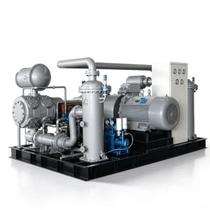
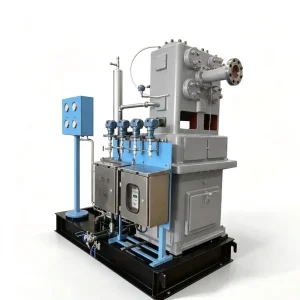
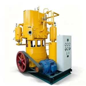
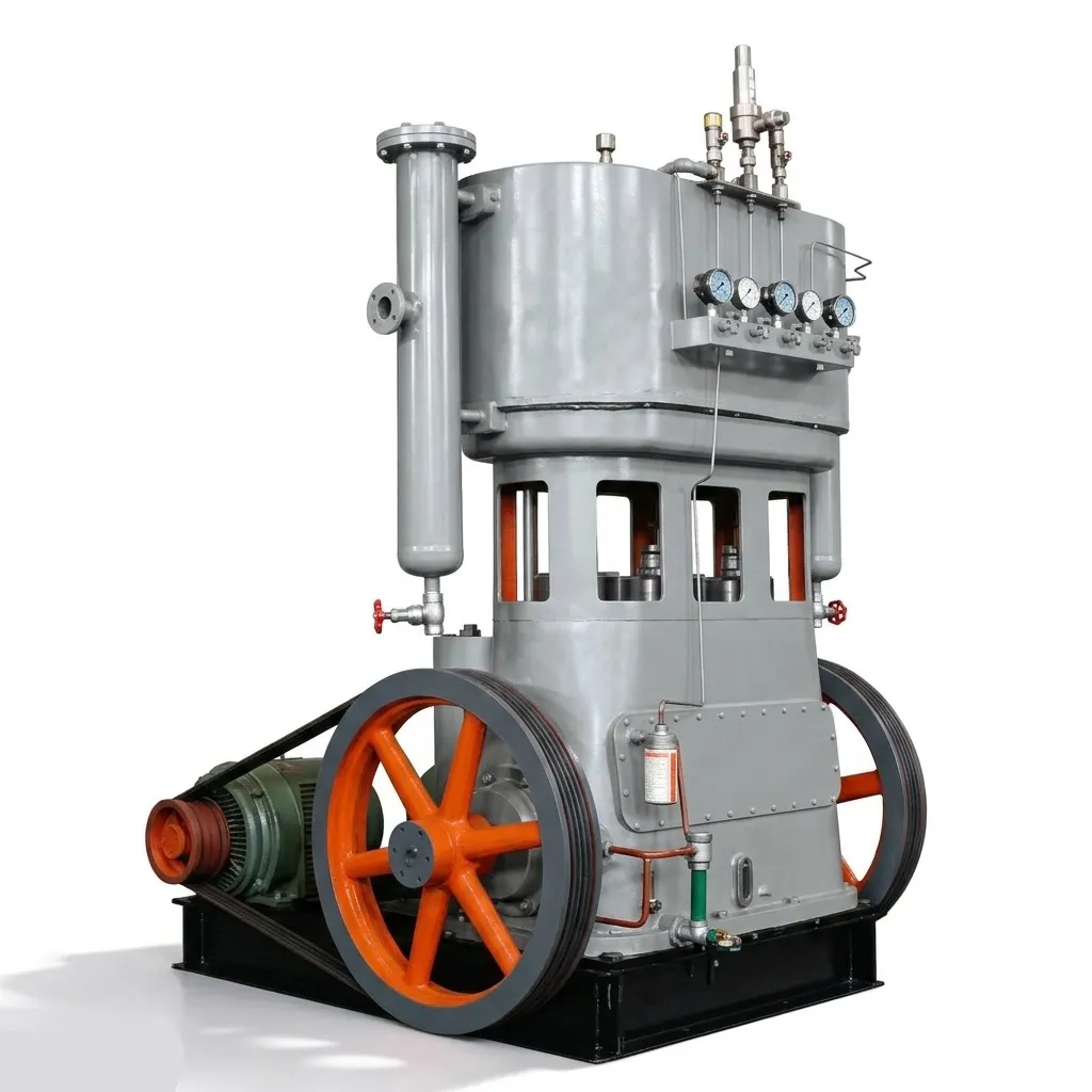
Our ZW Series nitrogen compressor eliminates this risk at the compression chamber itself — before any filtration question even arises. With 14 standard models spanning 1.0 to 5.0 m³/min and two pressure options at 15.0 and 16.5 MPa, the ZW Series is designed to be the definitive bottling station between your nitrogen generator and your high-pressure cylinder manifold.
Absolute Purity Preservation
100% oil-free cylinder construction with proprietary filled-PTFE seals. Zero oil mist in the nitrogen output — no downstream carbon filters required, no oil-water separators, no contamination risk across the equipment’s entire service life.
Multi-Stage Thermal Stability
4-stage and 5-stage architectures with inter-stage tubular intercoolers step up pressure gradually, preventing the thermal spikes that destroy valve plates and connecting rods in 2-stage retrofitted compressors attempting 150 Bar service.
24/7 Continuous Operation
Balanced multi-row crankshaft geometry, rugged cast iron frame construction, and predictable PTFE ring wear rates — designed from the outset for continuous cylinder filling operations without unplanned downtime across an 8,000-hour maintenance cycle.
Three Engineering Systems That Make 165 Bar Oil-Free N2 Bottling Reliable
Retrofitting a standard industrial compressor for 150 Bar nitrogen service is a common and costly mistake. The failure modes that result — valve plate fracture, piston rod seal blowby, and excessive thermal cycling — are all addressed at the design stage in the ZW Series.
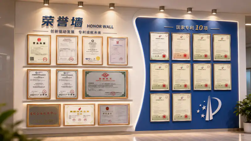
Complete ZW Series N2 Bottling Compressor Specifications — 14 Standard Models
All 14 models share the same standard 380V electrical supply and compact footprint suitable for existing gas cylinder filling station layouts. Two pressure tiers cover all standard industrial cylinder specifications. Every unit ships factory acceptance tested at rated discharge pressure.
Two-Row Four-Stage Models — 1.00 to 1.82 m³/min
| Model | Configuration | Capacity (m³/min) | Discharge (MPa) | Power (kW) | Weight (t) | Dimensions (mm) |
|---|---|---|---|---|---|---|
| ZW-1/150 | 2-row 4-stage | 1.00 | 15.00 | 30 | 4.00 | 2495×1800×2945 |
| ZW-1/165 | 2-row 4-stage | 1.00 | 16.50 | 30 | 4.00 | 2495×1800×2945 |
| ZW-1.67/150 | 2-row 4-stage | 1.67 | 15.00 | 37 | 4.00 | 2495×1800×2945 |
| ZW-1.67/165 | 2-row 4-stage | 1.67 | 16.50 | 37 | 4.00 | 2495×1800×2945 |
| ZW-1.82/150 | 2-row 4-stage | 1.82 | 15.00 | 37 | 4.00 | 2495×1800×2945 |
| ZW-1.82/165 | 2-row 4-stage | 1.82 | 16.50 | 45 | 4.00 | 2495×1800×2945 |
Three-Row Five-Stage Models — 3.00 to 5.00 m³/min (High-Capacity Filling Stations)
| Model | Configuration | Capacity (m³/min) | Discharge (MPa) | Power (kW) | Weight (t) | Dimensions (mm) |
|---|---|---|---|---|---|---|
| ZW-3/150 | 3-row 5-stage | 3.00 | 15.00 | 55 | 4.50 | 2575×2064×3407 |
| ZW-3/165 | 3-row 5-stage | 3.00 | 16.50 | 55 | 4.50 | 2575×2064×3407 |
| ZW-3.3/150 | 3-row 5-stage | 3.30 | 15.00 | 55 | 4.80 | 2575×2064×3407 |
| ZW-3.3/165 | 3-row 5-stage | 3.30 | 16.50 | 55 | 4.80 | 2575×2064×3407 |
| ZW-4.2/150 | 3-row 5-stage | 4.20 | 15.00 | 75 | 5.60 | 2900×2300×3500 |
| ZW-4.2/165 | 3-row 5-stage | 4.20 | 16.50 | 75 | 5.60 | 2900×2300×3500 |
| ZW-5/150 | 3-row 5-stage | 5.00 | 15.00 | 90 | 5.60 | 2900×2300×3500 |
| ZW-5/165 ⭐ | 3-row 5-stage | 5.00 | 16.50 | 90 | 5.60 | 2900×2300×3500 |
⭐ ZW-5/165: largest standard model — 5.0 m³/min at 16.5 MPa, 90 kW, 380V. Custom configurations from 11 kW to 132 kW available, including VFD-equipped skids for variable output matching PSA generator fluctuations.
Where 100% Oil-Free Nitrogen at 150–165 Bar Is Non-Negotiable
The demand for pure high-pressure nitrogen spans industries where contamination consequences range from expensive to catastrophic — and where oil-lubricated compression with downstream filtration is simply not an acceptable engineering approach.
Laser Cutting Assist Gas Supply
High-power fibre lasers use high-pressure nitrogen as the cutting assist gas — it displaces oxygen at the cut zone, preventing oxidation of stainless steel and aluminium cut edges, and blows molten material clear of the kerf. Oil mist in the nitrogen stream deposits hydrocarbon residues directly on the focusing lens and collimating optics. Lens replacement on a 20 kW fibre laser cutting head costs thousands of dollars; the ZW Series eliminates this risk entirely through oil-free compression at the source.
Electronics and Semiconductor Manufacturing
Cleanroom nitrogen purging, reflow soldering atmospheres, and semiconductor thin-film deposition chambers require nitrogen at parts-per-billion hydrocarbon purity. Any oil contamination in the process nitrogen disrupts surface chemistry, degrades thin-film adhesion, and can destroy an entire batch of high-value wafers. The ZW Series oil-free nitrogen compressor provides the hydrocarbon-free supply these processes demand without relying on downstream activated carbon filtration that degrades unpredictably over time.
Food Packaging — Modified Atmosphere (MAP)
Modified atmosphere packaging displaces oxygen from food containers with nitrogen, extending shelf life without preservatives. Food safety regulations in Australia and internationally specify oil-free gas supply for product-contact packaging atmospheres. The ZW Series satisfies these requirements with zero downstream filter dependency — eliminating the oil-in-gas monitoring burden and the compliance documentation associated with managing oil-lubricated compression in food production environments.
Industrial Gas Cylinder Filling Stations
Commercial gas distributors operate cylinder filling manifolds serving 40 L standard cylinders at 150 or 165 Bar. The ZW-5/165 at 90 kW can fill arrays of cylinders continuously — and the multi-stage efficiency of the ZW Series dramatically reduces the electrical cost per cubic metre bottled compared to 2-stage retrofitted approaches, directly improving the economics of a nitrogen distribution business with high throughput requirements.
Featured Case Study: Large-Scale Laser Fabrication Hub
Engineering Insight: The ROI calculation for this installation did not require a complex model. LN2 delivery costs, handling labour, cryogenic storage maintenance, and the unpredictability of delivery scheduling during peak demand periods all converted directly into payback months. The oil-free purity was the non-negotiable prerequisite that eliminated the alternative of a lower-cost oil-lubricated booster — because one lens replacement event would have cost more than the purity premium across the entire service life of the ZW units.
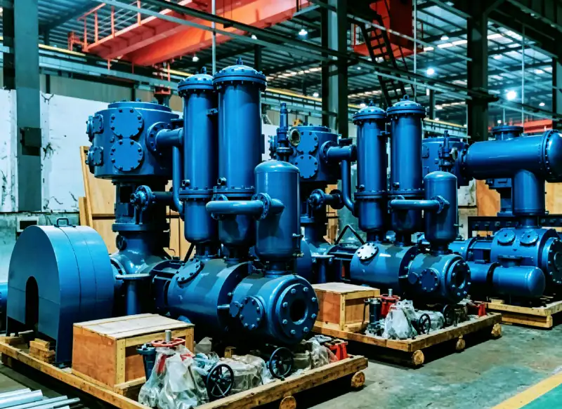
Installation Requirements and Maintenance Protocol
ZW Series compressors are not plug-and-play equipment. They are precision high-pressure industrial assets requiring proper foundation preparation, cooling water connection, and a disciplined preventative maintenance programme to sustain rated performance and oil-free purity across their full service life.
1Foundation and Cooling Water
Units up to 5.60 tonnes require a dedicated reinforced concrete foundation with anchor bolt positions matching our CAD layout drawings. Cooling water supply (typically 15–25°C, 0.2–0.4 MPa, 5–15 L/min per intercooler) must be confirmed and piped to all inter-stage coolers before commissioning. Inadequate cooling water flow is the most common cause of premature valve plate and packing failure in high-pressure nitrogen service.
24,000-Hour Valve Inspection
Precision valve plates on the highest-pressure stages (stage 4 on the 4-stage models, stages 4 and 5 on the 5-stage models) experience the greatest fatigue loading due to the large pressure differential across the valve face. At 4,000 operating hours, these plates are removed and measured for thickness reduction. Spring load is verified. Proactive replacement based on measured fatigue prevents the uncontrolled valve fracture events that cause gas blowby and contaminate the final cylinder-filling product stream with metal particles.
38,000-Hour PTFE Ring Overhaul
Full replacement of piston rings, guide rings, and all distance-piece packing seals at 8,000-hour intervals restores rated volumetric efficiency and re-establishes the 100% oil-free gas purity certification. Our global parts inventory maintains dedicated filled-PTFE composite ring sets for every ZW Series model — enabling planned maintenance windows to complete on schedule without ring material substitution risks that could compromise the purity performance of the bottled nitrogen product.
Dedicated ZW Series vs Retrofitted Generic Compressors — Why Specialisation Matters
The most common procurement mistake in high-pressure nitrogen bottling is selecting a standard air booster compressor and retrofitting it with nitrogen-compatible materials. The failure modes that result are predictable and well-documented in gas cylinder filling industry maintenance records.
| Evaluation Metric | ZW Series (Dedicated N2 Compressor) | Retrofitted Generic Compressors |
|---|---|---|
| Oil-Free Purity Guarantee | ✔ 100% oil-free by design — no downstream filters required, zero contamination risk. | ✘ Relies on oil-water separators and carbon filters that degrade and require monitoring. |
| Thermal Stability at 165 Bar | ✔ 4 or 5 stages with intercooling — discharge temperature per stage well within safe limits. | ✘ 2-stage design forces massive per-stage temperature spikes — valve plates fatigue in weeks. |
| Vibration and Frame Life | ✔ Balanced multi-row crankshaft — low vibration, predictable bearing life, no foundation cracking. | ✘ Unbalanced single-row frames produce high vibration — concrete cracking, pipe fatigue, bolt loosening. |
| Maintenance Interval | ✔ 8,000-hour PTFE ring replacement cycle — planned, predictable, budgetable. | ✘ Valve failure intervals of 500–2,000 hours common in high-pressure retrofitted duty. |
Why Gas Distributors and Industrial Gas Users Choose Australia Oil Free Air Compressor Co., Ltd.
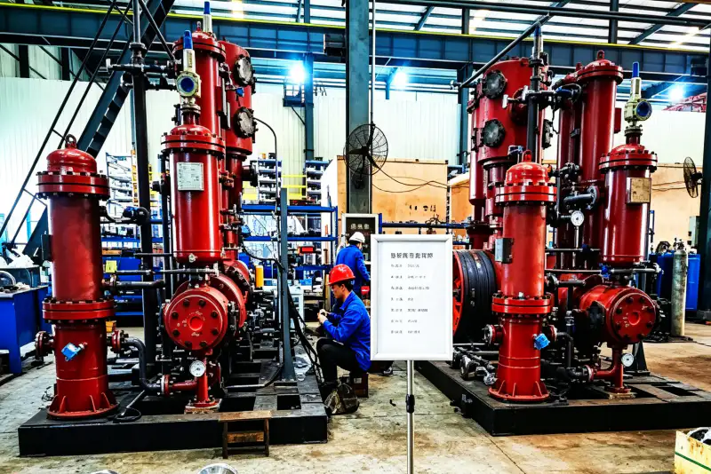
Engineering machinery that reliably compresses nitrogen to 16.5 MPa continuously for years leaves zero margin for material or manufacturing error. Every ZW Series high-pressure cylinder, valve manifold, and inter-stage cooler undergoes ultrasonic NDT and hydrostatic pressure testing before leaving our ISO-certified facility.
✅
Factory Hydrostatic Testing at 165 Bar
Every high-pressure cylinder and manifold pressure-tested to rated discharge pressure before assembly — structural integrity confirmed before the unit leaves the factory.
✅
Proprietary PTFE Ring Formulation
In-house developed filled-PTFE composite rings with validated 8,000-hour service intervals in 150–165 Bar nitrogen service — not generic ring materials from third-party suppliers.
✅
14 Standard Models, 380V Supply
All 14 standard models on standard 380V three-phase supply — no medium-voltage electrical infrastructure required for facilities with standard industrial power.
✅
Global Wear Parts Inventory
Valve plates, PTFE rings, and packing sets for all ZW models maintained in stock for international expedited dispatch — minimising planned maintenance downtime at remote filling stations.
How to Select the Right ZW Series Model for Your Nitrogen Station
With 14 models across two pressure tiers and a clear capacity progression from 1.0 to 5.0 m³/min, selection narrows to three questions that can be answered from your PSA generator datasheet and your cylinder filling schedule.
Match the Compressor Capacity to Your PSA Generator Output (m³/min)
The ZW Series compressor must match the nitrogen generator’s output flow rate. If your PSA plant produces 3.0 m³/min of nitrogen at 0.4 MPa, the ZW-3/150 or ZW-3/165 is the correct match. Undersizing wastes generator output; oversizing leaves the compressor underloaded and reduces filling station throughput economics. Check the generator’s rated output flow on the PSA plant datasheet before entering the model selection table.
Select the Correct Discharge Pressure — 15.0 or 16.5 MPa
Standard industrial nitrogen cylinders (40 L, 150 Bar) fill to 15.0 MPa. Some applications and cylinder specifications require 16.5 MPa (165 Bar) — particularly where cascade filling is used to maximise the usable volume per cylinder and where storage manifold pressures are higher. Confirm your cylinder working pressure rating and filling manifold specifications from the cylinder manufacturer before selecting between the /150 and /165 variants.
Confirm Cooling Water Supply Before Ordering
All ZW Series models require cooling water to the inter-stage shell-and-tube coolers. Typical requirements are 15–25°C inlet temperature at 0.2–0.4 MPa and 5–15 L/min per cooler circuit. Facilities without cooling tower water can use a closed-circuit cooler or plate heat exchanger — but this must be sized and confirmed before the unit is ordered. Cooling water specification is provided in our engineering datasheet; contact [email protected] for site-specific cooling sizing advice.
Build Your Oil-Free Nitrogen Bottling Station
Share your PSA generator output (m³/min), target cylinder fill pressure (150 or 165 Bar), and cooling water availability with the engineering team at Australia Oil Free Air Compressor Co., Ltd. — and receive a fully specified ZW Series recommendation within 48 hours.
Charlton Industrial Area, Australia | [email protected]
Related Reading
For operations where the choice between oil-free and oil-lubricated compression affects regulatory compliance and long-term operating cost: oil free vs oil lubricated compressor — true cost comparison over 10 years — essential reading before any nitrogen compression procurement decision.