Description
The Unique Engineering Challenge of High-Volume Low-Pressure CO2 Handling
Moving carbon dioxide at low pressures — from near-atmospheric up to 1.0 MPa — is a deceptively different discipline from the high-pressure supercritical service described in other compressor categories. The challenge here is not phase transition or geological backpressure: it is sheer volumetric scale combined with the persistent chemical aggression of carbonic acid. A coal-fired power plant carbon capture unit, a mega-brewery fermentation hall, and a world-scale urea production complex all share the same requirement: the ability to draw enormous volumes of wet, freshly recovered CO2 at near-zero gauge pressure and push it reliably into the next stage of the process — continuously, around the clock, year after year.
Standard rotary screw blowers and centrifugal fans — the default choices for high-volume low-pressure gas handling — share a fatal weakness in CO2 service: their high-speed impellers and tight rotor clearances are highly susceptible to the carbonic acid that forms whenever wet industrial gas streams contact metal surfaces. Our Low Pressure CO2 Compressors eliminate this vulnerability through stainless steel wetted construction and a positive-displacement piston architecture that is geometrically immune to the surge and erosion failures that end centrifugal service life in CO2 environments.
Carbonic Acid Immunity
All gas-wetted internals — cylinder liners, valve assemblies, piston rods, and inter-stage piping — manufactured from premium corrosion-resistant stainless steels. Carbonic acid pitting is structurally impossible at any moisture loading.
Massive Volumetric Efficiency
Ultra-large diameter cylinders with precision low-lift plate valves maximise intake volume per stroke while minimising aerodynamic throttling losses — delivering the lowest kW per cubic metre in high-volume CO2 service.
Four-Row Symmetrical Balance
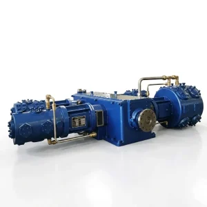
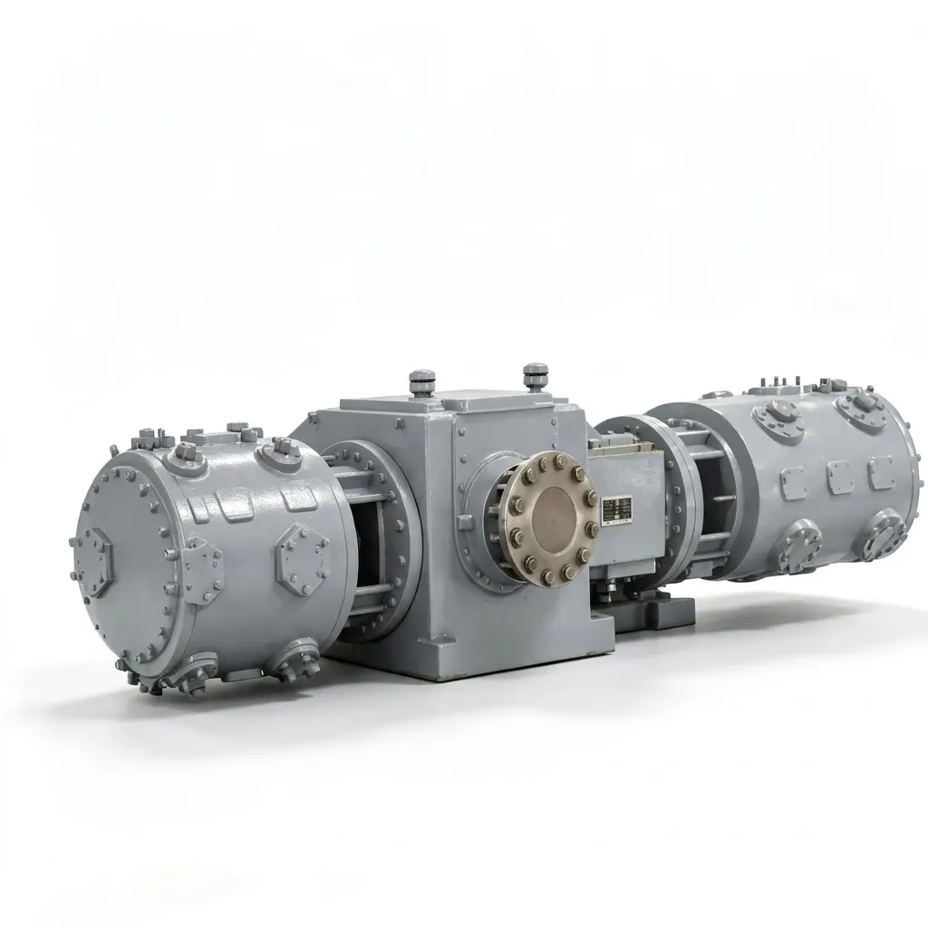
HW and 4MW series four-row horizontally opposed configurations cancel reciprocating inertial forces precisely — allowing 30-tonne machines pushing 600 m³/min to run with the vibration signature of a much smaller unit.
Three Engineering Systems Behind Reliable High-Volume CO2 Compression
Each engineering discipline below addresses a specific failure mode that has ended service life prematurely for centrifugal and rotary alternatives in large-scale carbon dioxide recovery operations worldwide.
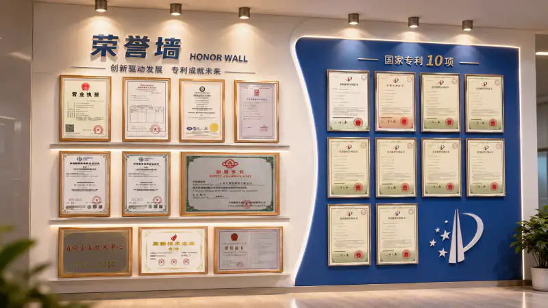
Complete Low-Pressure CO2 Compressor Model Range
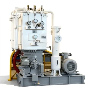
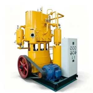
Our low-pressure carbon dioxide compressor matrix spans four series tiers — from compact ZW/LW units for pilot plant and mid-scale brewery applications, through heavy-duty DW bare-block machines, to the HW and 4MW mega-scale units built for world-class CCUS and industrial recovery stations.
Compact Series — ZW & LW Units (2 to 60 m³/min)
| Model | Stages | Capacity (m³/min) | Pressure (MPa) | Power (kW) | Weight (t) | Voltage |
|---|---|---|---|---|---|---|
| ZW-6/8 | 2-row 2-stage | 6 | 0.80 | 45 | 2.00 | 380V |
| LW-10/8 | 2-row 2-stage | 10 | 0.80 | 110 | 1.80 | 380V |
| LW-20/2 | 2-row 1-stage | 20 | 0.20 | 75 | 1.80 | 380V |
| LW-20/8 | 2-row 2-stage | 20 | 0.80 | 132 | 3.00 | 380V |
| LW-30/4 | 2-row 2-stage | 30 | 0.40 | 132 | 3.40 | 380V |
| LW-40/4 | 2-row 2-stage | 40 | 0.40 | 160 | 3.40 | 380V |
| LW-50/5 | 2-row 2-stage | 50 | 0.50 | 240–250 | 6.50 | 380 / 6k / 10k |
| LW-60/4 | 2-row 2-stage | 60 | 0.40 | 240–250 | 4.82 | 380 / 6k / 10k |
Heavy-Duty Series — DW Bare-Block Units (60 to 325 m³/min)
| Model | Stages | Capacity (m³/min) | Pressure (MPa) | Power (kW) | Weight (t) | Voltage |
|---|---|---|---|---|---|---|
| DW-60/6 | 2-row 2-stage | 60 | 0.60 | 350 | 6.00 | 380 / 6k / 10k |
| DW-68/4 | 2-row 2-stage | 68 | 0.40 | 315 | 6.80 | 380 / 6k / 10k |
| DW-100/6 | 2-row 2-stage | 100 | 0.60 | 550 | 13.00 | 6k / 10k |
| DW-116/6 | 2-row 2-stage | 116 | 0.60 | 630 | 13.00 | 6k / 10k |
| DW-150/4 | 2-row 2-stage | 150 | 0.40 | 710 | 18.00 | 6k / 10k |
| DW-190/2.5 | 2-row 1-stage | 190 | 0.25 | 650 | 15.00 | 6k / 10k |
| DW-290/2 | 2-row 1-stage | 290 | 0.20 | 1,000 | 17.00 | 6k / 10k |
| DW-325/2 | 2-row 1-stage | 325 | 0.20 | 1,100 | 18.00 | 6k / 10k |
Mega-Scale Series — 4MW & HW Four-Row Units (180 to 600 m³/min)
| Model | Config | Capacity (m³/min) | Pressure (MPa) | Power (kW) | Weight (t) |
|---|---|---|---|---|---|
| 4MW-180/6.5 | 4-row 2-stage | 180 | 0.65 | 1,000 | 26.00 |
| 4MW-240/6.5 | 4-row 2-stage | 240 | 0.65 | 1,300 | 26.00 |
| HW-380/2.5 | 4-row 1-stage | 380 | 0.25 | 1,300 | 28.00 |
| HW-600/1 ⭐ | 4-row 1-stage | 600 | 0.10 | 1,100 | 30.00 |
⭐ HW-600/1: largest single-machine low-pressure CO2 compressor in our standard range — 600 m³/min at 0.10 MPa, 30 tonnes, 6 kV/10 kV supply. Custom configurations beyond 600 m³/min available on request.
Four Major Applications Driving Global Low-Pressure CO2 Compression Demand
Across decarbonisation, food and beverage recovery, and industrial chemistry, these compressors sit at the heart of processes where both volumetric scale and chemical reliability are non-negotiable.
Carbon Capture, Utilisation, and Storage (CCUS)
Amine scrubbing units at power plants and cement works strip CO2 from flue gas at low absolute pressures — typically 0.1 to 0.3 MPa. Our HW-600/1 and DW series draw this captured gas directly from the absorber stripper outlet and boost it to 0.5–1.0 MPa for downstream liquefaction, pipeline injection, or geological storage. Two HW-600/1 units together move 1,200 m³/min — the typical output of a large post-combustion capture train serving a 1 GW coal plant.
Brewery and Beverage CO2 Recovery
Yeast fermentation in mega-breweries and bioethanol plants releases enormous volumes of CO2 at near-atmospheric pressure. Rather than flaring or venting this recoverable product, our oil-free CO2 compressors — configured specifically for wet fermentation gas — collect and compress this stream to approximately 1.0 MPa for scrubbing, deodorisation, and re-carbonation of finished beverages. A single large brewery can recover enough CO2 annually to meet its entire carbonation requirement using on-site fermentation recovery.
Urea and Fertiliser Production Feedstock
Urea synthesis requires a continuous, uninterrupted supply of CO2 into the synthesis reactor. At the pre-injection stage, this gas must be moved in bulk at 0.4–0.8 MPa from the CO2 recovery unit to the urea reactor inlet. Our DW and LW series provide the sustained volumetric delivery that large-scale ammonia-urea complexes depend on — maintaining exact reactor feed ratios across 24/7 continuous operation without the surge events that centrifugal alternatives suffer under variable production loads.
Industrial CO2 Pipeline Feed and Purification
Food-grade and industrial-grade CO2 purification plants receive raw gas from various recovery sources at variable low pressures and must deliver it at a precise, stable pressure to downstream liquefaction units. Our compressors serve as the pressure-stabilising buffer between variable source pressure and constant liquefaction demand, handling wet raw gas with stainless wetted paths while maintaining the consistent 0.6–1.0 MPa inlet pressure that liquefaction columns require for stable operation.
Featured Case Study: National Power Plant CCUS Carbon Capture Project
Engineering Insight: The centrifugal machines did not fail due to overload or specification error — they failed because no impeller alloy available at reasonable cost provides sufficient carbonic acid resistance in wet CO2 service. The positive-displacement piston architecture, combined with stainless steel cylinder liners and valve assemblies, removes corrosion from the failure mode list entirely. This is not a maintenance improvement; it is a structural elimination of the mechanism that ended the centrifugal installation’s service life.
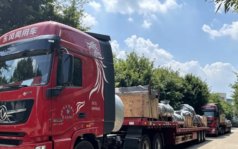
Installation Engineering and Preventative Maintenance Protocol
Deploying machinery at this scale — up to 30 tonnes, 1,300 kW, and 600 m³/min of corrosive gas — requires the most rigorous installation and maintenance programme of any large-scale industrial gas compression application.
1
Foundation and Electrical Preparation
The 4MW and HW series machines, weighing 26–30 tonnes, require vibration-dampening reinforced concrete foundations with dynamic loading data supplied by our engineering team to your civil contractors months before delivery. Motors above 550 kW require 6 kV or 10 kV medium-voltage switchgear with soft-starters or VFD panels sized to manage startup inrush current on the local grid. These electrical requirements must be confirmed and infrastructure commissioned before equipment arrival on site.
2
Daily Moisture Trap Monitoring
Automated moisture trap blowdown valves on inter-stage separators must be confirmed operational at every shift start. If condensate accumulates in a large-bore cylinder — because a trap has failed closed or a blowdown cycle has missed a high-condensation event — the resulting liquid slug can cause hydraulic hammer severe enough to crack a cylinder head. Daily confirmation of trap actuation status is the single most important operational check on any wet CO2 compressor installation.
3
4,000–8,000 Hour Valve and Ring Service
The stainless steel valve plates in large-bore CO2 cylinders are subject to high-cycle aerodynamic loading — millions of actuations per week in continuous service. Valve plate thickness inspection and spring load verification at 4,000-hour intervals identify fatigue before uncontrolled fracture can occur. PTFE guide rings, which centre the massive pistons within the bore and carry radial loads without metal-to-metal contact, are replaced at 8,000-hour intervals to maintain volumetric efficiency and prevent cylinder wall scoring.
4
Remote PLC Telemetry and Predictive Dispatch
Our advanced PLC arrays monitor main bearing temperatures, motor load factors, inter-stage gas temperatures, and vibrational harmonics in real time. Optional remote cloud telemetry transmits this data to our engineering headquarters continuously — allowing anomaly detection algorithms to identify developing wear trends weeks before they would cause an unplanned shutdown, enabling proactive dispatch of wear parts and field technicians to remote CCUS or brewery sites before a process impact occurs.
Reciprocating vs Centrifugal vs Rotary Screw — CO2 Technology Comparison
For high-volume low-pressure CO2 applications, three technology options exist. In laboratory conditions, all three can move gas. In wet industrial CO2 service at continuous baseload, the comparison resolves quickly.
| Evaluation Metric | Our Reciprocating CO2 Compressors | Centrifugal / Rotary Screw Alternatives |
|---|---|---|
| Wet CO2 Corrosion Resistance | ✔ Stainless steel wetted parts — carbonic acid pitting structurally impossible at any moisture loading. | ✘ Impellers and screws erode rapidly in wet CO2. Standard alloys unserviceable within months. |
| Surge / Instability Risk | ✔ Positive displacement — no surge phenomenon. Stable delivery across any intake flow variation. | ✘ Surge at low flow is violent and damaging. Recovery systems add cost and complexity. |
| Power Efficiency at 1.0 MPa | ✔ Physical piston stroke delivers near-theoretical volumetric efficiency with minimal aerodynamic slip. | ✘ Rotor clearance slip increases sharply as discharge pressure approaches 1.0 MPa — wasting energy. |
| Variable Flow Turndown | ✔ VFDs and cylinder unloaders achieve 50–100% turndown without instability or efficiency collapse. | ✘ Turndown below design point causes surge or requires wasteful bypass loops and anti-surge systems. |
Why CCUS Projects and Industrial Producers Choose Australia Oil Free Air Compressor Co., Ltd.
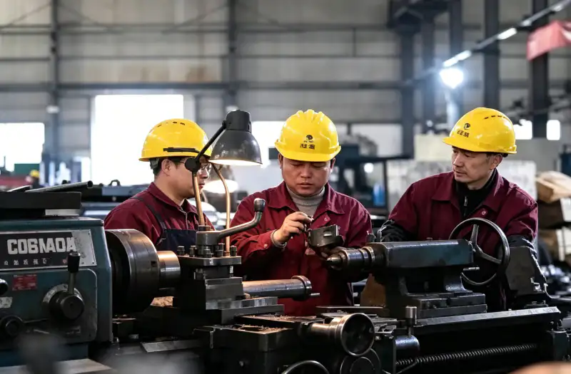
Manufacturing machinery capable of moving 600 m³/min of corrosive gas continuously for decades allows absolutely zero margin for material or manufacturing defects. Our ISO-certified production framework subjects every crankshaft, cylinder block, and stainless manifold to ultrasonic flaw detection, X-ray weld inspection, and full-load dynamic testing before shipment.
✅
Full Stainless Steel Wetted Build
Every gas-contacting surface in premium corrosion-resistant stainless alloys — carbonic acid immunity is a structural feature, not a maintenance-dependent claim.
✅
X-Ray Weld and Ultrasonic NDT
Every pressure vessel and weld joint radiographically and ultrasonically inspected before assembly — material flaws detected and resolved before equipment leaves our facility.
✅
Full-Load Dynamic Testing
Every unit factory acceptance tested at rated load and pressure — vibration, temperatures, and valve performance documented against specification before shipment.
✅
Scalable from 2 to 600+ m³/min
Compact 380V ZW skids through mega-scale 1,300 kW four-row HW machines — a single supplier relationship covering the full range of CO2 recovery and CCUS project scales.
Strategic Selection Checklist for Low-Pressure CO2 Projects
Three sequential decisions reduce a broad model range to the correct specification for any low-pressure carbon dioxide compression project — from pilot CCUS to world-scale brewery recovery.
Calculate Peak CO2 Recovery Volume (m³/min)
A micro-brewery CO2 recovery system may need only 6 m³/min (ZW-6/8 skid). A large brewery or bioethanol plant may require 60–100 m³/min (LW or DW series). A major power station post-combustion capture unit may need 600 m³/min (two HW-600/1 units). Define the peak flow from your carbon capture or fermentation process design basis before entering the model selection table — the correct tier is determined by volumetric throughput.
Confirm Downstream Discharge Pressure (MPa)
Gas feeding a downstream liquefaction column typically requires 0.6–1.0 MPa (two-stage models). A low-pressure purification buffer accepting gas from an amine stripper may only need 0.2–0.4 MPa (one-stage models). The staging architecture — and therefore the entire model shortlist — is determined by the downstream process pressure requirement. Confirm this from your process simulation or plant licensor specification before procurement.
Verify Electrical Infrastructure for High-Capacity Units
Compact ZW and smaller LW units below 200 kW operate on standard 380V three-phase supply. DW and HW series machines above 500 kW require 6 kV or 10 kV medium-voltage switchgear and substation capacity for motor startup inrush. Confirm your substation single-line diagram is reviewed by our engineering team before finalising the model selection — contact [email protected] with your electrical infrastructure summary at the inquiry stage.
Specify Your Low-Pressure CO2 Compression System
Share your recovery volume, source pressure, target discharge pressure, and moisture content with the engineering team at Australia Oil Free Air Compressor Co., Ltd. — and receive a fully specified stainless-wetted CO2 compressor recommendation within 48 hours.
Charlton Industrial Area, Australia | [email protected]
Related Reading
For operations where sustainability metrics and carbon footprint reduction are part of the project justification alongside technical performance: oil free air compressors carbon footprint — what the numbers show — a quantitative analysis of emissions data directly relevant to CCUS and decarbonisation project reporting.