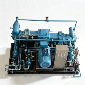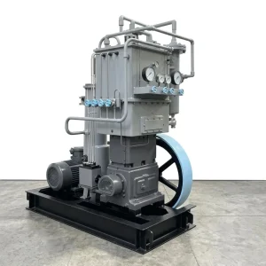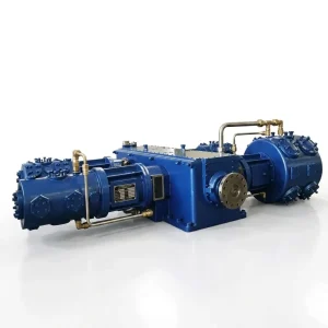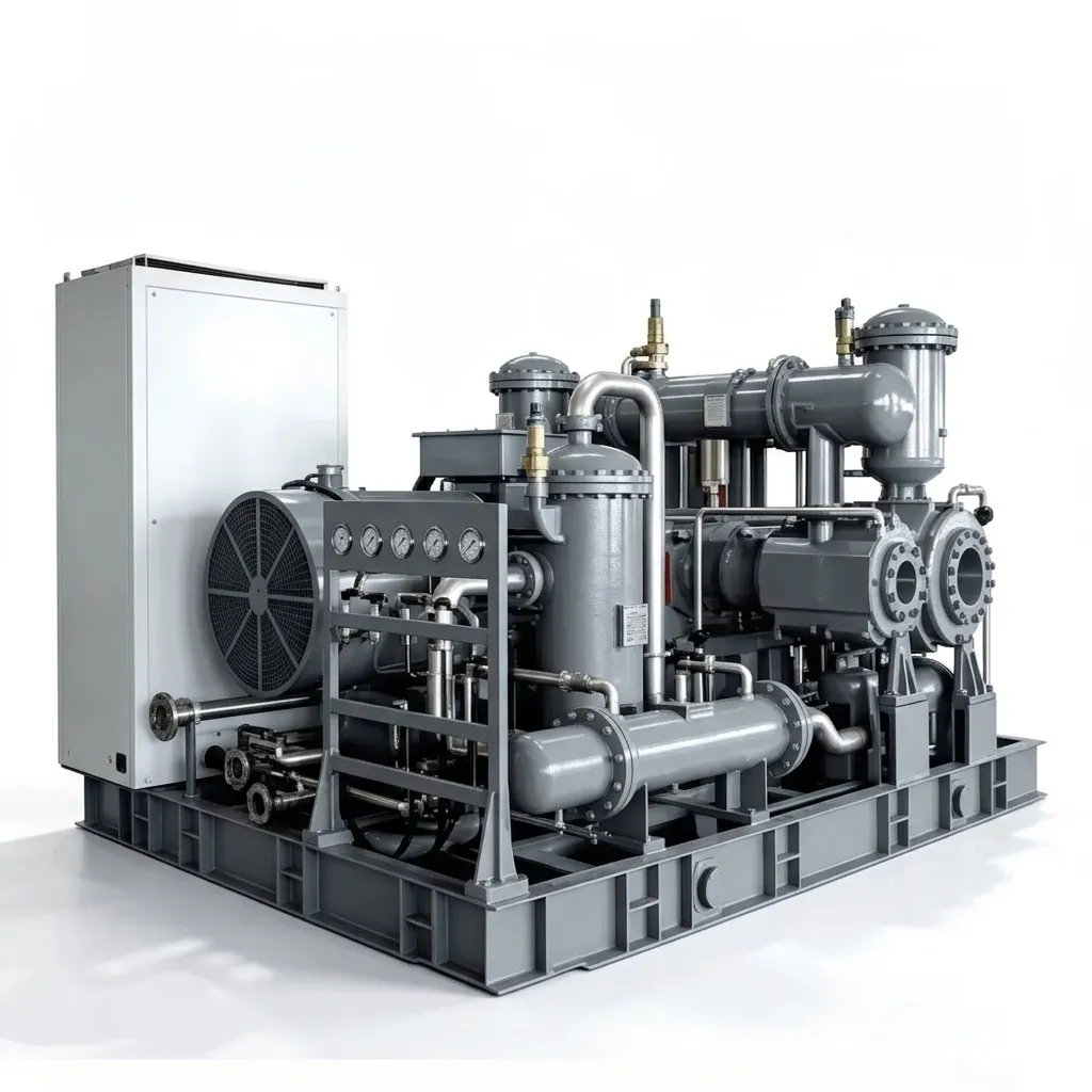
Description
Why CO2 Compression at High Pressure Demands Purpose-Built Engineering
Carbon dioxide sits at the intersection of two of the most significant industrial challenges of our era — global decarbonisation and heavy chemical manufacturing. As a feedstock, it is indispensable for urea fertiliser synthesis and methanol production. As a captured emission, it must be compressed to supercritical pressures for permanent geological storage or enhanced oil recovery. Both roles demand the same thing from a CO2 compressor: the ability to handle a gas that behaves in ways unlike any other industrial fluid. CO2 approaches its critical point at just 7.38 MPa and 31.1°C — conditions routinely encountered during high-pressure compression cycles. At this threshold, the fluid shifts from gas to a supercritical state with liquid-like density but gas-like viscosity. In a standard reciprocating air compressor not designed for this transition, the result is liquid hammer — an uncompressible slug striking the cylinder head at full piston velocity, capable of shattering valve plates and cracking cylinder blocks in a single stroke.
Compounding this, industrial CO2 recovered from flue gas, fermentation, or chemical processes carries moisture. Under pressure, that moisture combines with CO2 to form carbonic acid — a compound that rapidly corrodes standard cast iron and carbon steel internals. Our Medium and High Pressure CO2 Compressors are purpose-built to overcome both threats simultaneously, delivering 2 to 200 m³/min at 1.20 to 9.00 MPa for the most demanding EOR, CCUS, and synthesis applications on the planet.
Phase-Change Fluid Dynamics
Specialised cylinder geometries, advanced valve dynamics, and mandatory inter-stage knockout drums prevent dense-phase CO2 from triggering liquid hammer across the supercritical transition threshold at 7.38 MPa.
Carbonic Acid Immunity
Every gas-wetted component — cylinder liners, valve seats, piston rods, inter-stage manifolds — fabricated from highly alloyed duplex stainless steel. Acidic pitting and corrosion are structurally impossible at any moisture loading.
Heavy-Mass Kinematic Balance
Four-row horizontally opposed crankcase geometry cancels the immense reciprocating forces needed to push heavy CO2 to 90 Bar — delivering whisper-smooth operation from a 27-tonne machine across decades of baseload service.
Three Engineering Systems That Tame High-Pressure CO2
Compressing carbon dioxide across the supercritical boundary requires solving thermodynamic, chemical, and mechanical challenges that cannot be addressed by adapting general-purpose machinery. Each system below eliminates a specific failure mode found in incidents at CCUS and EOR installations worldwide.
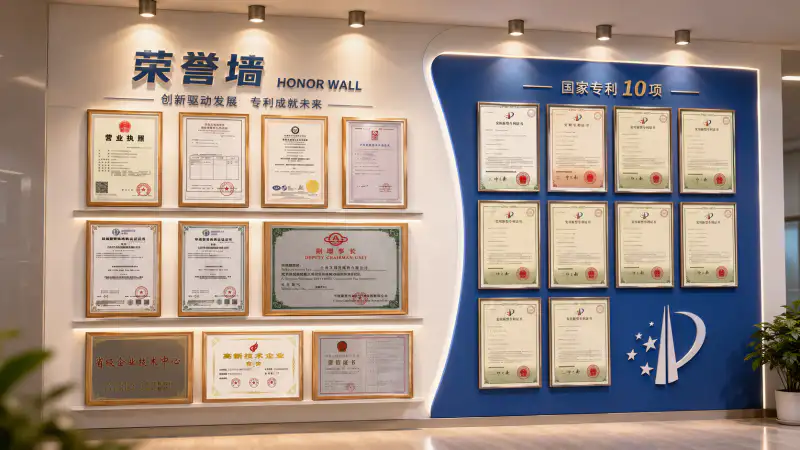
Complete CO2 Compressor Model Range and Technical Specifications
Three configuration tiers cover every medium-to-high pressure CO2 application — from compact chemical loop skids to mega-scale EOR injection station powerhouses. All models are available with duplex stainless wetted components and multi-stage moisture separation as standard.
Compact Series — ZW & LW Units (1.80 to 6.00 MPa)
| Model | Configuration | Capacity (m³/min) | Pressure (MPa) | Power (kW) | Weight (t) |
|---|---|---|---|---|---|
| LW-6/18 | 2-row 2-stage | 6.0 | 1.80 | 65 | 1.80 |
| ZW-4/25 (Skid) | 2-row 3-stage | 4.0 | 2.50 | 55 | 3.97 |
| ZW-5.5/24 | 3-row 3-stage | 5.5 | 2.40 | 75 | 3.50 |
| LW-16/30 | 2-row 3-stage | 16.0 | 3.00 | 220 | 6.00 |
| LW-20/36 (Skid) | 2-row 3-stage | 20.0 | 3.60 | 250 | 9.50 |
| ZW-2/60 (Skid) | 2-row 3-stage | 2.0 | 6.00 | 45 | 2.90 |
Heavy-Duty Series — DW Bare-Block Units (3.00 to 4.00 MPa)
| Model | Configuration | Capacity (m³/min) | Pressure (MPa) | Power (kW) | Weight (t) |
|---|---|---|---|---|---|
| DW-25/40(30) | 2-row 4-stage | 25.0 | 4.00 / 3.00 | 315 / 280 | 6.00 |
| DW-30/40(30) | 2-row 4-stage | 30.0 | 4.00 / 3.00 | 400 / 355 | 11.00 |
| DW-46/40(30) | 2-row 4-stage | 46.0 | 4.00 / 3.00 | 600 / 550 | 13.00 |
| DW-60/40(30) | 2-row 4-stage | 60.0 | 4.00 / 3.00 | 710 / 650 | 17.00 |
Mega-Scale Series — 4MW Four-Row Units (EOR / CCS Baseload)
| Model | Configuration | Capacity (m³/min) | Pressure (MPa) | Power (kW) | Weight (t) |
|---|---|---|---|---|---|
| 4MW-85/40(30) | 4-row 4-stage | 85.0 | 4.00 / 3.00 | 1,000 | 26.00 |
| 4MW-100/40(30) | 4-row 4-stage | 100.0 | 4.00 / 3.00 | 1,400 | 26.50 |
| 4MW-120/40(30) | 4-row 4-stage | 120.0 | 4.00 / 3.00 | 1,400 | 26.50 |
| 4MW-150/40(30) | 4-row 4-stage | 150.0 | 4.00 / 3.00 | 1,700 | 27.00 |
Custom configurations from 11 kW to 2,000 kW available. Specific models engineered for pressures up to 9.0 MPa for deep geological storage injection. Contact our team with process conditions for a bespoke specification.
Industrial Applications Across the High-Pressure CO2 Landscape
From depleted oil reservoir injection fields to urea synthesis reactors and deep saline aquifer storage sites, our CO2 compressors operate at the pressure-critical nodes where the performance of the entire downstream process depends on mechanical reliability.
Enhanced Oil Recovery (EOR) Injection
Supercritical CO2 injected into depleted reservoirs dissolves into residual crude oil, reducing its viscosity and driving it toward production wells. This requires sustained pressures of 6.0 to 9.0 MPa to overcome geological backpressure. Our 4MW series delivers the unrelenting mechanical force needed to push thousands of tonnes of CO2 per day underground continuously — resistant to the surge events that destroy centrifugal alternatives when wellhead backpressure fluctuates.
Urea and Fertiliser Synthesis
Urea production via the Bosch-Meiser process demands a continuous, high-pressure feed of liquid or dense-phase carbon dioxide into the synthesis reactor to react with ammonia at 14–18 MPa. The duplex stainless construction of our CO2 compressors ensures feedstock purity is maintained without carbonic acid contamination degrading the reactor catalyst or reducing nitrogen-to-carbon ratios in the final fertiliser product.
Carbon Capture and Deep Geological Sequestration
To permanently store CO2 in saline aquifers or depleted gas fields, the gas must be compressed to a supercritical state — typically 7.4 MPa or above — where it occupies minimal volume and remains stable underground indefinitely. Our multi-stage compressors serve as the final injection pump in grid-scale CCUS projects, handling the combined output of multiple capture trains at the sustained pressures required for geological integrity.
Chemical Synthesis and Dense-Phase CO2 Utilisation
Supercritical CO2 is used as a solvent in pharmaceutical extraction, polymer foaming, and specialty chemical manufacturing — applications where precise pressure and purity control are critical. Our compact ZW and LW skid units serve these chemical process loops, providing pilot-scale through mid-scale throughputs at the exact pressure targets required by each synthesis pathway.
Featured Case Study: Mega-Scale EOR Field Injection Station
Engineering Insight: The centrifugal machines failed on two independent fronts simultaneously — material degradation from carbonic acid and aerodynamic surge from backpressure variation. Neither failure mode is possible in a well-specified reciprocating CO2 compressor: positive displacement is immune to surge by definition, and duplex stainless construction is immune to carbonic acid by material chemistry. The choice of compression technology determined whether this EOR project succeeded or failed — not the project scale or budget.
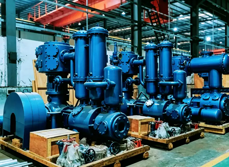
Installation Engineering and Lifecycle Maintenance Protocol
Deploying machinery that draws up to 1,700 kW, weighs nearly 30 tonnes, and compresses corrosive CO2 to 90 Bar demands the most rigorous installation and maintenance programme of any industrial compression application outside hydrogen service.
1
Civil Engineering and High-Voltage Supply
The 4MW series machines, weighing up to 27 tonnes, require deep, vibration-isolating reinforced concrete foundations with precisely calculated dynamic loading specifications. We supply complete CAD foundation drawings and pulsation study results to civil contractors early in the project programme. High-voltage 6 kV or 10 kV switchgear must be in place before equipment delivery, with soft-starters or VFD panels specified to limit grid inrush current on motor starting events for the largest units.
2
4,000-Hour High-Stage Valve Inspection
CO2 is a heavy polyatomic gas that generates rapid aerodynamic loading on valve plate faces — particularly in final-stage high-pressure cylinders. At 4,000 operating hours, precision valve plates are removed and measured for fatigue thinning. Flutter-induced micro-cracking, detectable by dye penetrant inspection, is the primary mechanism of valve failure in high-density gas service. Replacing plates on a predictable schedule eliminates the uncontrolled valve fracture events that force emergency shutdowns at EOR and CCUS stations.
3
8,000-Hour Seal and Ring Overhaul
Heavy-duty PTFE piston rings, guide rings, and packing glands are replaced at 8,000-hour intervals to maintain optimal volumetric sealing against the extreme 60–90 Bar backpressures of EOR and deep sequestration service. Our global parts inventory stocks the specific heavy-duty ring grades used in CO2 service — not standard air compressor replacements — enabling planned maintenance windows to complete on schedule without component substitution risks.
4
IoT Predictive Diagnostics and Remote Monitoring
Our control panels feature advanced PLC architectures with cloud telemetry capability. Frame vibration signatures, inter-stage temperatures, interstage knockout drum levels, and drive motor load factors are monitored continuously and transmitted to our engineering headquarters. Anomaly detection flags developing wear trends — typically weeks before they would cause a process shutdown — enabling our global service network to dispatch wear parts and field technicians to remote EOR and CCUS sites on a predictive rather than emergency basis.
Reciprocating vs Centrifugal for High-Pressure CO2 — A Direct Comparison
When scaling to 150 m³/min and pressures approaching 90 Bar, centrifugal compressors are often considered for their throughput potential. The EOR case above illustrates why the comparison consistently resolves in favour of reciprocating technology for high-pressure CO2 service.
| Evaluation Metric | Our Reciprocating CO2 Compressors | Centrifugal High-Pressure Alternatives |
|---|---|---|
| Backpressure Fluctuation | ✔ Positive displacement pushes through variable wellhead and pipeline backpressures. Zero surge risk. | ✘ Highly sensitive to backpressure — fluctuations cause violent surge, damaging impellers and seals. |
| Carbonic Acid Resistance | ✔ Duplex stainless throughout — no acid attack on any wetted surface regardless of moisture loading. | ✘ Standard impeller alloys suffer rapid blade erosion from carbonic acid in wet CO2 streams. |
| Dense Phase Tolerance | ✔ Cyclonic inter-stage separators knock out any condensed CO2 before it enters the next cylinder. | ✘ A single dense-phase droplet hitting a high-speed impeller acts like a projectile — rotor destroyed instantly. |
| High-Pressure Efficiency | ✔ Positive displacement maintains full volumetric efficiency at any pressure within the design range. | ✘ Aerodynamic slip across impeller clearances causes efficiency collapse above 4.0 MPa for CO2. |
Why CCUS and EOR Projects Choose Australia Oil Free Air Compressor Co., Ltd.
Forcing hundreds of tonnes of corrosive CO2 deep into the earth’s crust allows no margin for equipment failure. Our production facilities operate under elite ISO-certified quality protocols — every crankshaft, cylinder block, and stainless manifold undergoes ultrasonic flaw detection, X-ray weld inspection, and full-load dynamic testing before leaving the factory floor.
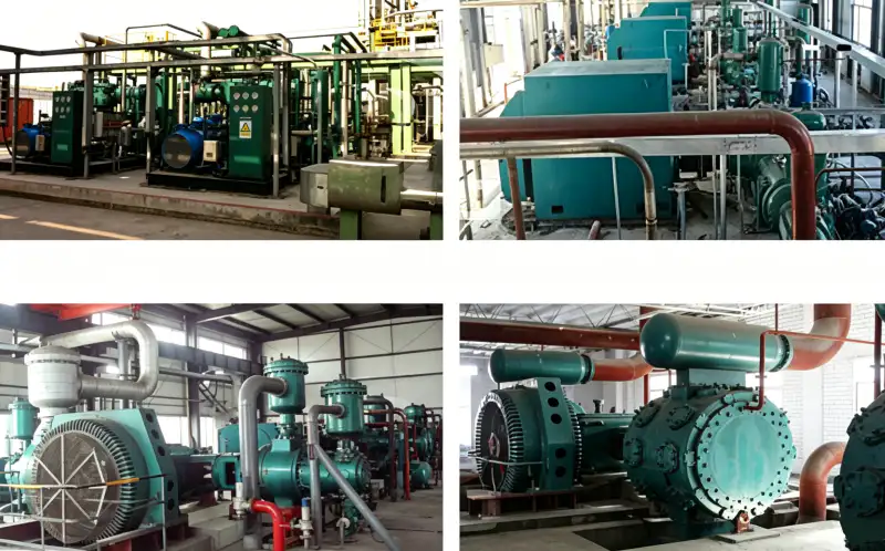
Duplex Stainless as Standard
All gas-wetted components in highly alloyed duplex stainless steel — carbonic acid immunity across all moisture loading scenarios without requiring dry gas specification guarantees.
X-Ray Weld and UT Inspection
Every pressure manifold, cylinder block, and crankshaft undergoes radiographic and ultrasonic flaw detection before assembly — documented and traceable per unit.
Full-Load Dynamic Testing
Every unit undergoes factory acceptance testing at rated load and pressure before shipment — vibration, temperatures, and valve performance verified against design specification.
Custom up to 2,000 kW / 9.0 MPa
Bespoke configurations from compact 11 kW chemical loop skids to 2,000 kW deep sequestration injection station powerhouses — all engineered to exact site process conditions.
Strategic Selection Checklist for High-Pressure CO2 Applications
Three sequential decisions determine the correct model for any medium-to-high pressure CO2 project. Working through these with our engineering team before procurement avoids the most common specification errors in CCUS and EOR compression projects.
A single chemical synthesis loop may need only 4–6 m³/min (ZW compact skid). A CCUS project aggregating output from multiple capture trains may need 120–150 m³/min (4MW series). Size to peak injection demand — and account for turndown requirements during partial capture operation or off-peak periods when the VFD range matters most.
EOR reservoir injection pressure is dictated by the geological formation — typically 6.0 to 9.0 MPa for deep reservoirs. Urea synthesis requires 3.0 to 4.0 MPa. Supercritical storage requires exceeding the 7.38 MPa critical point. The discharge pressure target determines staging architecture entirely — provide the wellhead or reactor inlet pressure specification from your licensor or reservoir engineer before entering model selection.
Motors above 500 kW require 6 kV or 10 kV medium-voltage infrastructure. The 4MW-150 at 1,700 kW demands serious substation capacity and soft-starter or VFD integration confirmed before delivery. Separately, confirm your CO2 stream moisture content — even if upstream dehydration is specified, our duplex stainless standard build provides complete protection against under-performing dryers and eliminates the need for dry-gas guarantees in the equipment purchase specification.
Engineer Your CO2 Compression Station for the Long Term
Share your CO2 flow rate, inlet conditions, discharge pressure target, and moisture content with the engineering team at Australia Oil Free Air Compressor Co., Ltd. — and receive a fully specified, duplex stainless CO2 compressor recommendation within 48 hours.
Charlton Industrial Area, Australia | [email protected]
Related Reading
For projects where total operating cost over a 20-year asset life is a key procurement criterion alongside capital cost: oil free air compressor total cost of ownership — the full breakdown — a detailed framework for evaluating compression equipment across energy, maintenance, and reliability dimensions that applies directly to large-scale EOR and CCUS procurement decisions.