Description
What the MW Series Solves That Smaller Oxygen Compressors Cannot
Modern integrated steel complexes processing five million tonnes of crude steel per year require oxygen delivery at flow rates that smaller reciprocating units — even banks of them — cannot match economically. A basic oxygen furnace heat requires a controlled oxygen burst of up to 1,000 Nm³/min across a 20-minute blowing period; the associated continuous oxygen infrastructure feeding it operates at 80–135 m³/min under steady-state conditions. At this scale, the engineering challenge is not merely achieving a required flow and pressure — it is doing so with zero oil contamination of the oxygen stream, because any hydrocarbon carryover into a basic oxygen furnace oxygen circuit represents both a metallurgical quality risk and a serious safety concern in the presence of molten steel and process gases at over 1,600°C.
The same requirement emerges in different forms across large-scale chemical oxidation plants — ethylene oxide synthesis, partial oxidation for syngas, terephthalic acid production — where the industrial oxygen compressor is the feed gas supply for reactions where hydrocarbon contamination would poison catalysts, degrade selectivity, and represent a direct explosion risk in oxygen-enriched process streams. In large-scale medical oxygen production for cylinder filling and hospital piping distribution, the oxygen flow rates served by a single MW Series unit replace entire banks of smaller compressors, simplifying the oxygen station design and reducing the number of potential leak points in the system.
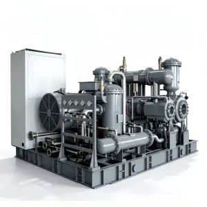
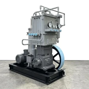
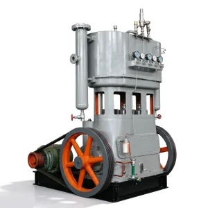
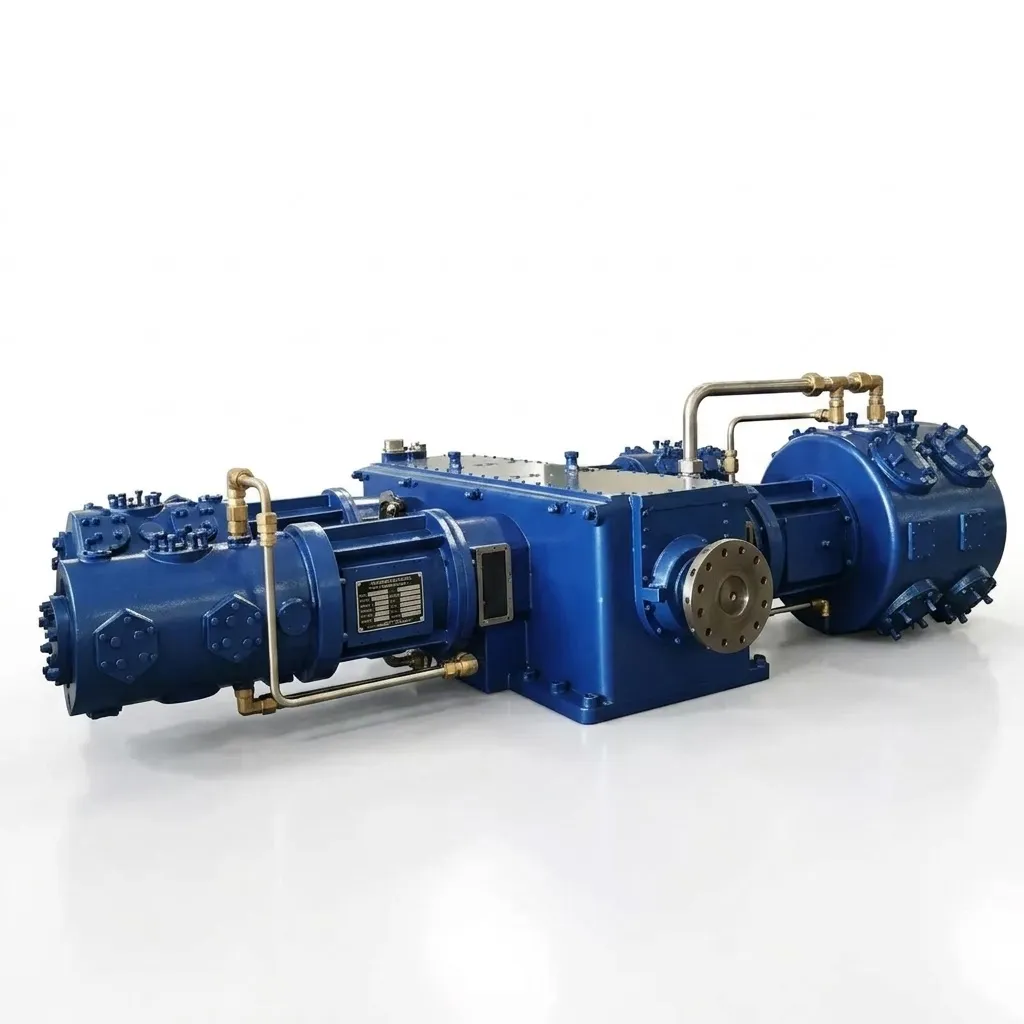
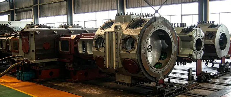
The 4MW Series — with its 26-tonne four-column frame, 6kV/10kV medium-voltage drives, and 6,800 × 4,000 × 3,200 mm footprint — is a different class of equipment from any other compressor in this product line. It is specified by process engineers, procured by project management teams, and commissioned by specialist oxygen equipment engineers as a capital infrastructure asset with a design life measured in decades.
4-Column Symmetric Balance
Four symmetrically arranged columns distribute reciprocating inertial forces across the frame — eliminating the unbalanced moments that conventional 2-column designs transmit to foundations at high capacity, reducing foundation reinforcement requirements and extending bearing life at sustained duty.
6kV / 10kV Medium-Voltage Drive
900–1,200 kW motors at medium voltage — the natural supply infrastructure for large industrial plants — eliminating the low-voltage bus capacity and transformer costs that equivalent LV motor starts would require at this power level.
100% Oil-Free — Zero Downstream Filtration
Copper-alloy oxygen-compatible wetted surfaces, PTFE-based packing, and complete crankcase-to-cylinder isolation eliminate hydrocarbon contamination structurally. In the steel mill case study below, removing the downstream oil filtration train reduced capex by 35% versus the previous lubricated installation.
Four Engineering Systems Behind the 4MW Platform
Each element below represents an engineering decision that distinguishes the 4MW platform from conventional large-capacity air compressors repurposed for oxygen service — a practice that introduces predictable failure modes at industrial scale.
4MW Series — Complete Model Specifications
Three standard models cover the full range of large-scale industrial oxygen compression requirements — from cryogenic ASU booster service to high-pressure BOF oxygen injection and chemical oxidation reactor feed. All three share the same 4-column frame footprint and 6kV/10kV medium-voltage electrical infrastructure.
| Model | Architecture | Capacity (m³/min) | Intake Pressure (MPa) | Discharge Pressure (MPa) | Power (kW) | Voltage | Weight (t) | Dimensions (mm) |
|---|---|---|---|---|---|---|---|---|
| 4MW-135/1.7~8 | 4-column 2-stage | 135 | 0.17 MPa | 0.80 | 1,200 | 6kV / 10kV | 26.0 | 6800×4000×3200 |
| 4MW-80/30 | 4-column 4-stage | 80 | Atmospheric | 3.00 | 900 | 6kV / 10kV | 26.0 | 6800×4000×3200 |
| 4MW-100/30 ⭐ | 4-column 4-stage | 100 | Atmospheric | 3.00 | 1,200 | 6kV / 10kV | 26.5 | 6800×4000×3200 |
ASU outlet booster service — receives pressurised oxygen at 0.17 MPa from a cryogenic air separation unit cold box and delivers at 0.80 MPa to the plant distribution header. Highest volumetric throughput in the series at 135 m³/min.
Atmospheric-to-3.0 MPa four-stage service — suitable for basic oxygen furnace injection, high-pressure chemical oxidation reactors, and large-scale oxygen cylinder filling stations. The 4MW-100/30 is the most widely specified model for integrated steel mill primary oxygen compression.
Custom MW Series configurations from 11 kW to 2,000 kW single-unit power available for applications outside the standard three-model range. Contact our engineering team with oxygen flow, pressure, intake conditions, and site constraints.
Six Industries Where the 4MW Scale Becomes the Correct Engineering Choice
The 4MW platform is not the right choice for every oxygen application — it is the right choice when the oxygen demand exceeds 80 m³/min continuously, when the facility’s electrical infrastructure is already designed for medium voltage, and when a single reliable machine is preferable to a bank of smaller units that multiplies mechanical complexity, maintenance tasks, and potential failure points.
Integrated Steel Mill — Basic Oxygen Furnace
A five-million-tonne-per-year integrated steel complex requires continuous oxygen compression at 80–100 m³/min to supply basic oxygen furnace blowing, iron ladle metallurgy, and secondary refining operations. Two 4MW-100/30 units operating in parallel with automatic load sharing — as in the case study below — provide the full required flow with n+1 redundancy, ensuring continuous oxygen availability even during planned maintenance on one unit.
Petrochemical — Ethylene Oxide and Syngas
Ethylene oxide production by direct oxidation and partial oxidation syngas plants require continuous high-purity oxygen at reactor inlet pressures of 1.0–3.0 MPa at flow rates that only a machine of 4MW scale can supply from a single unit. Oil contamination in these oxygen feeds would poison silver catalysts in ethylene oxide service and create explosive carbon-oxygen byproducts in partial oxidation — the 4MW oil-free design eliminates this risk structurally.
Cryogenic ASU Booster Service
The 4MW-135/1.7~8 is specifically configured for air separation unit booster service — receiving the oxygen stream from the cold box at 0.17 MPa and delivering to the plant distribution ring at 0.80 MPa. This duty requires extremely high volumetric throughput at relatively modest pressure ratio, which the two-stage 4MW architecture serves with superior isothermal efficiency versus multi-stage alternatives at equivalent flow rates.
Oxy-Fuel Combustion — Glass and Cement
Glass furnaces and cement kilns using oxy-fuel burners to increase thermal efficiency and reduce NOx emissions require oxygen at 0.5–1.5 MPa and flow rates that scale with the furnace size. Large float glass lines and cement plants with multiple kiln strings can exceed 80 m³/min oxygen demand — the 4MW-80/30 at 0.8 MPa intermediate delivery provides both the throughput and the pressure needed in a single machine per production line.
Large-Scale Medical Oxygen Production
Regional medical oxygen production hubs supplying networks of hospitals, aged care facilities, and cylinder distribution require both high throughput and pharmacopoeial-grade purity assurance. A single 4MW-100/30 replaces multiple smaller compressors in a large medical gas plant, simplifying the compression station design, reducing the number of gas connections that represent potential leak points, and providing a single documentation trail for regulatory compliance audits.
Municipal Wastewater — High-Rate Ozone Treatment
Advanced wastewater treatment plants using ozone for micropollutant removal and disinfection at metropolitan scale require oxygen as the feed gas for ozone generators at flow rates that can exceed 50–100 m³/min. The 4MW-80/30 serves as the primary oxygen compression stage in these installations, feeding ozone generation systems that treat water for populations of hundreds of thousands of people.
Featured Case Study: 5 Mt/year Integrated Steel Complex Oxygen Station
Engineering Insight: The 35% capex reduction in this installation came almost entirely from the elimination of the downstream oil filtration train — coalescing separators, activated carbon beds, oil monitors, and the associated piping and instrumentation that a lubricated compressor installation requires to deliver acceptably clean oxygen to the furnace. When the total installed cost of lubricated compression plus filtration is compared to 4MW oil-free compression alone, the 4MW platform is consistently the more economical choice for large-scale continuous service. The oil-free specification at this scale is not a safety premium — it is an economics advantage.
Installation Requirements and Lifecycle Maintenance Framework
At 26 tonnes, 1,200 kW, and 6kV/10kV supply, the 4MW platform is a major capital project requiring coordinated civil, mechanical, and electrical engineering before equipment delivery. Our project engineering team provides full documentation to support each discipline from the initial foundation design through to first oxygen delivery.
1
Foundation and Civil Engineering
A 26-tonne four-column reciprocating compressor generates dynamic loads that require a purpose-designed reinforced concrete foundation — not an equipment pad. Our project package includes detailed foundation drawings specifying concrete grade, reinforcement layout, anchor bolt pattern, and grout pocket dimensions. Foundation design accounts for both static weight and the dynamic load spectrum from the rotating and reciprocating masses, verified by dynamic analysis at the motor operating speed. Foundation drawings are released early in the project schedule to allow civil construction to proceed while equipment fabrication continues in parallel.
2
Medium-Voltage Electrical and Cooling Water
Both 6kV and 10kV motor supply configurations are available — confirm with your electrical engineering team which medium-voltage bus is available at the compressor installation location. Motor control centres are designed for integration into the plant DCS via MODBUS RTU or Profibus-DP. Cooling water supply for intercoolers requires confirmed flow rate, supply pressure, and temperature — the engineering package specifies exact cooling water demand for each model to allow the cooling tower or heat exchanger capacity to be confirmed before equipment delivery.
3
Planned Maintenance Intervals
The 4MW modular cylinder design allows individual stage maintenance — valve inspection, ring replacement — without dismantling the entire compressor or taking the parallel unit off-line. Valve assemblies on high-pressure stages are inspected at 4,000-hour intervals. Piston rings and packing seals are replaced at 8,000-hour intervals. Main bearing shells are inspected at 16,000-hour major overhaul. A computerised maintenance management system tracks component life across each unit and issues automated maintenance alerts based on actual operating hours, ensuring the 99.2% availability demonstrated in the steel mill case study is sustained across the equipment’s full design life.
Why Major Industrial Operators Choose Australia Oil Free Air Compressor Co., Ltd. for 4MW Scale
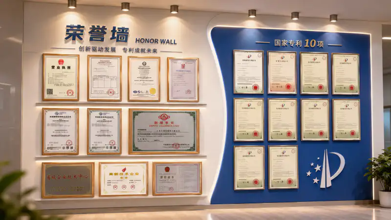
At 1,200 kW and 26 tonnes, the 4MW platform is specified by process engineers who require full traceability from material certificates through factory acceptance testing to commissioning documentation. Our ISO-certified production framework and quality assurance programme are built for this documentation standard — not retrofitted to it.
API 618 Design Compliance
Cylinder bore honing, roundness, and straightness specifications exceed API 618 reciprocating compressor standard requirements — the reference standard for large industrial process gas compressors.
Full NDT and Hydrostatic Testing
Ultrasonic NDT and radiographic weld inspection on all pressure-bearing components. Hydrostatic pressure test at 1.5 × design pressure with test records issued per vessel. Factory acceptance testing at rated conditions before shipment.
CGA G-4.1 Oxygen Cleaning Certified
Five-stage oxygen cleaning protocol — alkaline degrease, acid pickle, DI water rinse, hot-air dry, UV fluorescence inspection — documented and supplied per unit with particle count and hydrocarbon detection records.
18,000+ Hours Field Validated
The 4MW-100/30 units in the steel mill case study have accumulated over 18,000 operating hours at 99.2% availability — the most direct validation of the platform’s reliability at continuous industrial duty.
Specifying the Correct 4MW Model for Your Oxygen Station
Three process engineering parameters define which of the three standard 4MW models is correct — and whether a custom configuration is required. All three need to be confirmed from your process data before a firm specification can be issued.
Confirm the maximum continuous oxygen demand from all downstream consumers simultaneously — steelmaking oxygen flow rates vary with heat size and furnace operating cycle, so a process flow diagram showing all consumers and their simultaneous operating conditions is required for correct sizing. Add a 10–15% design margin above the calculated maximum to provide operational flexibility. If peak demand exceeds 100 m³/min continuously, a parallel 4MW-100/30 installation (as in the steel mill case) may be more appropriate than a single custom unit above the standard range.
The intake pressure differentiates the two-stage 4MW-135/1.7~8 (inlet 0.17 MPa from ASU cold box) from the four-stage 4MW-80/30 and 4MW-100/30 (atmospheric inlet). The discharge pressure determines the stage count and intercooler configuration within the four-stage models. Confirm both inlet pressure, temperature, and gas composition (oxygen purity, moisture content, trace components from the upstream source) — all affect the thermodynamic calculations that determine rated performance at your specific site conditions.
At 900–1,200 kW, the 4MW platform requires either 6kV or 10kV medium-voltage motor supply — confirm which bus voltage is available at the installation location before ordering. Motor control centre integration with the plant DCS should be specified at the inquiry stage, including the communication protocol (MODBUS RTU, Profibus-DP, or alternative) and the tag list for all process and status signals. Contact [email protected] with your process data sheet, site electrical single-line diagram, and DCS specification for a complete project engineering quotation.
Commission Your 4MW Industrial Oxygen Station
Share your oxygen flow rate (m³/min), inlet and discharge pressures, medium-voltage supply specification, and DCS integration requirements with the engineering team at Australia Oil Free Air Compressor Co., Ltd. — receive a fully engineered 4MW Series project proposal within 5 working days.
Charlton Industrial Area, Australia | [email protected]
Related Reading
For process engineers evaluating the true cost comparison between oil-free and oil-lubricated compression at industrial scale — including filtration infrastructure, maintenance intervals, and contamination risk quantification: oil free vs oil lubricated compressor — true cost comparison over 10 years — the analytical framework that underlies the 35% capex reduction achieved in the steel mill case study above.