Troubleshooting Guide
Systematic fault diagnosis for maintenance engineers and plant operators — covering every common oil-free compressor fault mode, root cause analysis, corrective actions, and escalation criteria to prevent repeat failures.
An oil-free air compressor that is not performing correctly costs a facility in three compounding ways: elevated energy consumption, compromised air quality, and the risk of unplanned downtime at the worst possible moment. Effective troubleshooting — identifying the root cause of a fault rather than addressing the symptom — is what separates a five-minute corrective action from a five-day repair. This guide covers every common fault mode encountered in industrial oil-free screw compressors, from the most frequent nuisance alarms to the rare but serious failure conditions that require immediate shutdown. For each fault, you will find the probable causes ranked by frequency, the diagnostic steps to confirm the cause, and the corrective action to resolve it — whether that is a simple operational adjustment, a scheduled parts replacement, or an escalation to a specialist service team. This guide applies equally to water-lubricated oil-free compressors and dry screw designs, with technology-specific notes where the diagnosis or corrective action differs.
How to Use This Troubleshooting Guide
Step 1 — Identify the symptom category: pressure fault, temperature fault, air quality fault, operational fault, or alarm/shutdown. Step 2 — Work through the probable causes in the order listed — they are ranked from most to least frequent. Step 3 — Apply the diagnostic check to confirm the cause before taking corrective action. Step 4 — Execute the fix; re-test to confirm resolution. Step 5 — Record the fault, cause, and corrective action in the maintenance log. Recurring faults within the same interval indicate a systemic issue requiring a deeper investigation than the immediate fix.
⚠ Safety first: always isolate the compressor from its electrical supply and depressurise the system before accessing any internal components. Never attempt to open filter housings or valve bodies under pressure.
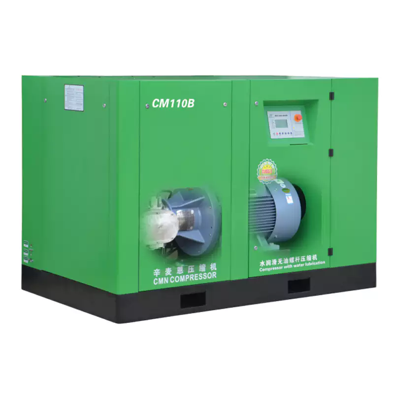
EP Series oil-free screw compressor — intelligent controller with fault code display, performance trending, and alarm history for systematic fault diagnosis.
Category 1: Pressure Faults
Pressure faults — either system pressure below setpoint or pressure fluctuation — are the most visible operational symptoms because they directly affect production. A single root cause can present as any pressure symptom depending on severity, making systematic diagnosis essential.
FAULT 1.1 — System pressure consistently below setpoint
HIGH FREQUENCY
Probable Causes (most → least frequent)
- Compressed air system leak — new leak or existing leak worsened
- Blocked / overdue inlet air filter — reducing compressor FAD
- Increased downstream demand — new equipment added to system
- Minimum pressure check valve stuck open or leaking past seats
- Pressure regulator setpoint drift or regulator failure
- Air-end volumetric efficiency loss (long-term — rotor clearance increase)
Diagnostic & Corrective Action
- Leak test: Apply soapy water or ultrasonic detector to all fittings, joints, and quick-disconnect couplings. Repair any weeping connections before other diagnosis.
- Filter check: Read inlet differential pressure gauge; replace if above threshold.
- Demand audit: Log compressor load % — if running at 95–100%, capacity is insufficient for current demand. Size up or add second unit.
- MPC valve test: Isolate compressor; check valve for back-flow with pressure gauge downstream.
- Regulator check: Verify setpoint against design; clean or replace if drifted.
- Performance baseline: Compare current FAD to commissioning data. >5% reduction → inspect air-end.
FAULT 1.2 — Pressure fluctuates / unstable discharge pressure
MEDIUM FREQUENCY
Probable Causes
- Receiver tank undersized for demand profile — rapid cycling
- Inlet valve or modulation valve sticking / hunting
- VSD drive PID control loop tuning incorrect
- Demand side intermittent large consumers causing pressure dip
- Leaking safety relief valve chattering at elevated pressure
Diagnostic & Corrective Action
- Cycling log: Record load/unload frequency; if cycling faster than 6× per hour, add receiver volume (rule: 6× FAD in litres).
- Valve inspection: Observe inlet valve operation during modulation; clean or replace if sticking.
- VSD tuning: Check PID parameters in drive controller; adjust P-gain down if hunting is observed.
- Demand profile: Log downstream pressure dips vs. production schedule to identify the large consumer; add local receiver or dedicated feed line.
- SRV test: If SRV chatters at setpoint, it may be undersized or worn — replace; verify new SRV set pressure.
Category 2: Temperature & Thermal Faults
High-temperature shutdowns are among the most disruptive faults in compressed air systems because they occur suddenly and cannot be reset until the root cause is corrected. In regulated manufacturing environments, a mid-batch thermal shutdown triggers a deviation event — making temperature fault prevention a quality system priority, not just a maintenance concern.
FAULT 2.1 — High temperature alarm / thermal protection shutdown
HIGHEST FREQUENCY FAULT
Probable Causes (in order of frequency)
- Blocked / fouled cooler fin faces — most common cause nationally
- Plant room ambient temperature exceeds 40°C (summer peak or inadequate ventilation)
- Plant room ventilation fan failure — single-point failure often undetected
- Cooler fan belt slipping or broken (belt-driven fan models)
- Temperature sensor or thermostat calibration drift — false alarm
- Coolant flow restriction in water-cooled models
- Rotor efficiency loss creating elevated compression heat
Diagnostic & Corrective Action
- Cooler inspection (first action): Before any other check, inspect cooler fin faces for debris. Clean with low-pressure compressed air or water rinse from inside out. Confirm reduced discharge temperature at next restart.
- Ambient measurement: Record plant room temperature at compressor inlet level — must be <40°C. If exceeded, check ventilation fan operation and clear any blocked ventilation apertures.
- Fan check: Confirm cooler fan is rotating and pulling air through fins at rated flow. Stroboscope or tachometer check useful.
- Belt check: Inspect belt tension and condition; replace if slipping or cracked.
- Sensor calibration: Cross-check temperature reading against a calibrated thermometer at the discharge port — if values differ >5°C, recalibrate or replace sensor before further diagnosis.
- Water circuit (WL models): Check coolant flow rate and temperature differential across heat exchanger; check for scale fouling.
FAULT 2.2 — Discharge temperature gradually rising over weeks/months
SLOW-DEVELOPING
Probable Causes
- Progressive cooler fouling between cleaning intervals
- Gradual ventilation deterioration (seasonal dust accumulation in fans / grilles)
- Seasonal ambient temperature increase (summer)
- Rotor clearance increase from coating wear (long-term >10,000 hrs)
- Thermostatic bypass valve wear — diverting hot air back before cooler
Corrective Action
- Accelerate cooler cleaning interval to 500 hours in dusty environments. Log temperature trend to confirm step improvement after cleaning.
- Schedule ventilation system cleaning in October and March (seasonally). Inspect filter grilles on plant room ventilation; clear debris.
- Seasonal temperature rise of 5–10°C is normal for Australian summers — ensure baseline was measured in summer conditions. Consider additional ventilation in extreme heat events.
- At >8°C baseline increase after confirmed-clean cooler, schedule air-end inspection.
- Inspect and test thermostatic valve; replace if it fails to fully close the bypass port at temperatures above its rated opening point.
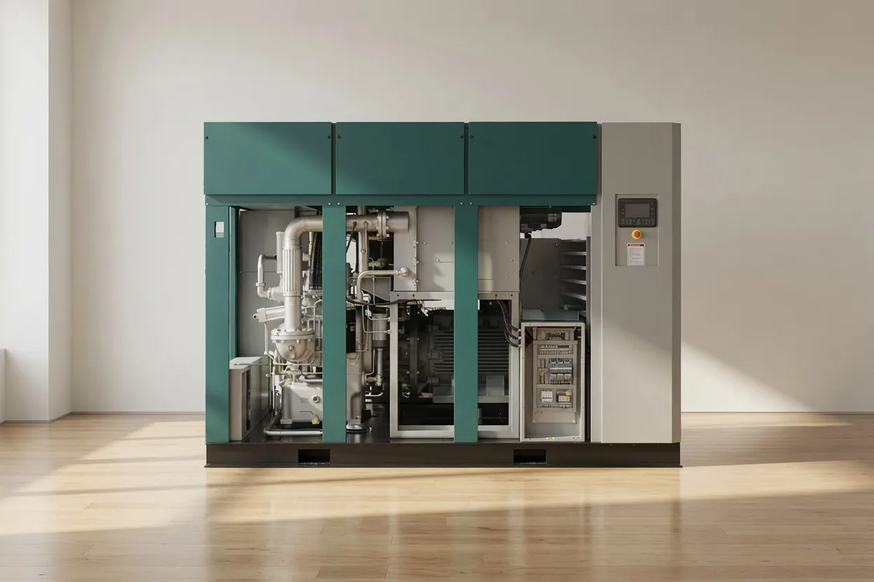
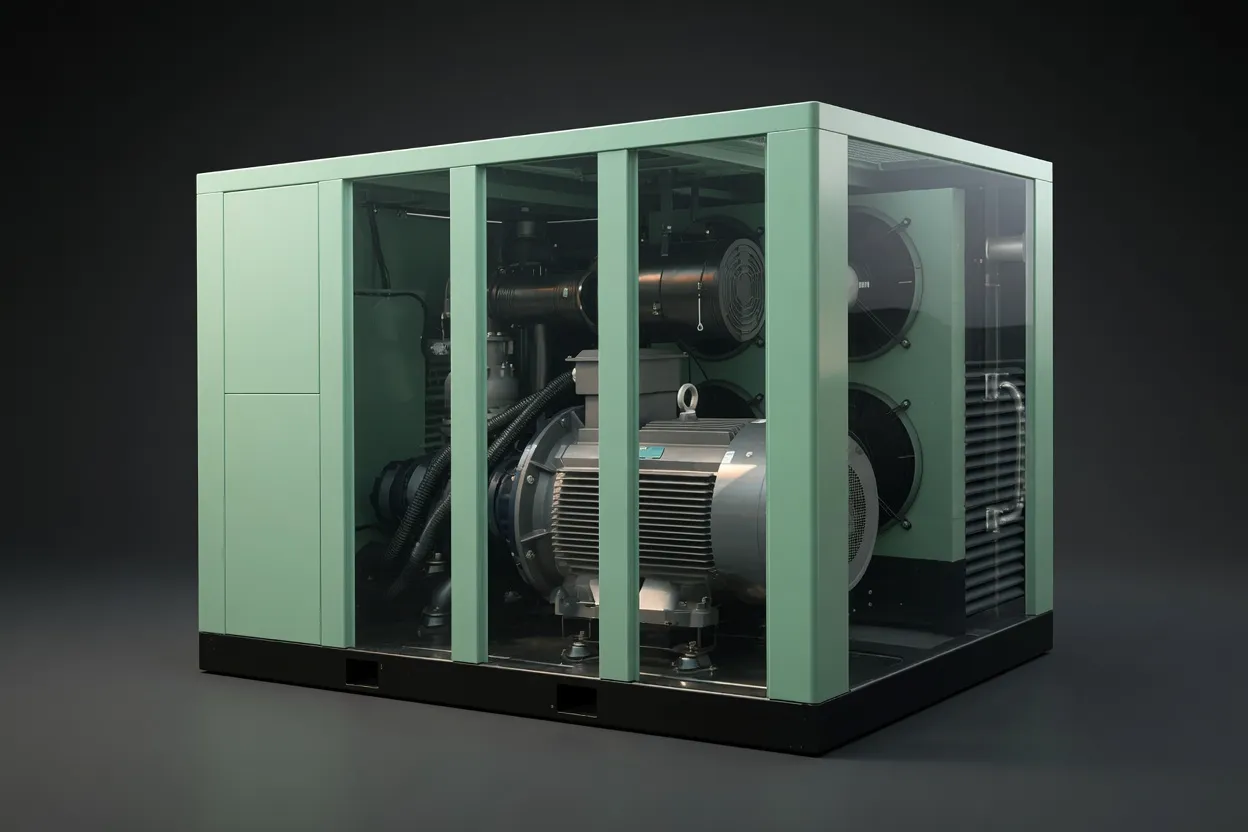
Compressor service access — key components accessible for diagnostic inspection: cooler, filter housing, valve assemblies, and condensate drain point.
Category 3: Air Quality Faults
Air quality faults are the most serious fault category for regulated industries because they may affect product quality, patient safety, or regulatory compliance. They are also often the hardest to detect without a monitoring programme in place, since many cannot be perceived through normal operational observation. Establishing baseline air quality data during commissioning is the prerequisite for meaningful air quality fault diagnosis.
FAULT 3.1 — Pressure dewpoint rising / moisture in distribution system
MEDIUM-HIGH FREQUENCY
Probable Causes
- Refrigerant dryer fault — refrigerant loss, compressor failure, or condenser fouling
- Dryer bypassed — manual bypass valve left open during maintenance and not closed
- Dryer undersized for actual compressed air flow (demand has grown)
- Desiccant dryer — desiccant media exhausted or regeneration cycle failure
- Auto-drain blockage — condensate accumulating in receiver / filter housings and carryover
- High ambient humidity event overwhelming dryer capacity
Diagnostic & Corrective Action
- Dryer check — first action: Confirm dryer is in service (power on, no fault lights, pressure differential across dryer normal). Check refrigerant dryer sight glass — bubbles indicate refrigerant loss. Measure dryer outlet dewpoint with calibrated hygrometer.
- Bypass valve check: Visually confirm all manual bypass valves are in normal operating position (closed).
- Capacity check: Compare actual system flow (from compressor controller) to dryer rated capacity at actual inlet temperature and pressure — if exceeding dryer capacity, add a second dryer in parallel or replace with higher-capacity unit.
- Desiccant check: Test outlet dewpoint across the desiccant bed — if dewpoint rise appears during regeneration cycle, confirm regeneration heater and timer operation. Replace desiccant if media is saturated and cannot regenerate fully.
- Auto-drain: Manually trigger auto-drain on receiver and filter housings; confirm condensate exits. Clean drain float valve / solenoid if blocked.
FAULT 3.2 — ISO 8573-1 oil content out-of-specification at annual test
CRITICAL — REGULATED INDUSTRIES
Probable Causes
- Atmospheric hydrocarbon contamination at compressor intake (most common in oil content failures at Class 0 level)
- Timing gear oil seal failure — oil from gear housing migrating toward air-end (dry screw)
- Rotor coating micro-particles — elevated particulate that includes polymer material (not hydrocarbon oil, but may trigger oil detection methods)
- Activated carbon filter — if fitted — exhausted; not replacing hydrocarbons
- Contaminated pipework from previous oil-lubricated system — residual oil in system
- Testing methodology error — sample point near atmospheric contamination source
Diagnostic & Corrective Action
- Intake air sample — first action: Take a background air quality sample at the compressor intake location using the same ISO 8573-1 method. If background contains elevated hydrocarbons, the source is atmospheric — relocate intake or install activated carbon pre-filter.
- Gear oil seal inspection (dry screw): Check for oil presence in the air-end access area; inspect shaft seals between gear housing and air-end. Replace seals if weeping.
- System flush: If system was previously oil-lubricated, a full system purge and degreasing of distribution pipework may be required. Repeat air quality test after flushing.
- Carbon filter: Replace activated carbon filter element; re-test within 48 hours.
- Retest protocol: For pharmaceutical and food sites — quarantine affected air circuit, raise a deviation, complete root cause investigation before returning to service.
Category 4: Operational & Electrical Faults
FAULT 4.1 — Compressor fails to start / no response to start command
HIGH FREQUENCY
Probable Causes
- Active fault alarm from previous shutdown — must be cleared before restart permitted
- Emergency stop button activated — physically locked out or jammed in
- Power supply fault — phase loss, blown fuse, tripped MCB
- Control circuit voltage fault — 24V DC supply failure in control board
- Motor thermal overload relay tripped — motor was overloaded or overheated
- Pressure switch fault — system at or above cut-in pressure, compressor correctly idle
Diagnostic Sequence
- Check controller display for active fault codes — clear any stored faults; attempt restart.
- Confirm all emergency stop buttons are released; check remote E-stop circuits.
- Check incoming power supply: measure voltage at all three phases at the main terminal block — confirm symmetrical voltage within ±5% of rated.
- Check control voltage: measure 24 V DC at controller terminals.
- Check motor overload relay: reset manually after allowing 15 minutes for motor to cool; investigate cause of overload before restarting.
- Check system pressure: if pressure is above cut-in setpoint, compressor is correctly idle — check setpoint programming.
FAULT 4.2 — Excessive noise or unusual vibration
MEDIUM FREQUENCY
Probable Causes by Sound Type
- Rattling / metallic clatter: Loose panel screws; anti-vibration mount degraded; loose pipework clamp
- Rhythmic knocking: Belt drive imbalance; coupling misalignment; loose flywheel (piston type)
- High-frequency screech: Bearing beginning to fail — shutdown immediately and inspect
- Increased low-frequency rumble: Air-end rotor imbalance; damaged rotor lobe — specialist inspection required
- Hissing near joints: Compressed air leak — locate and seal
Corrective Action
Immediate action for any high-frequency screech or increasing low-frequency rumble: Shut down the compressor immediately. Do not attempt to operate through these sounds — bearing failure can progress to rotor contact within hours of a screech onset. Contact a qualified service engineer for inspection before restart.
For rattling and low-severity vibration: inspect and tighten all panel fasteners, check anti-vibration mount condition, inspect belt tension (belt-drive units), confirm all pipe support clamps are secure. Perform a vibration measurement at the air-end casing and compare to the baseline reading taken during commissioning.
Category 5: Water-Lubricated Compressor-Specific Faults
Water-lubricated oil-free screw air compressors — such as the CM132DV and CM45D — offer significant advantages in air purity and discharge temperature, but have a set of fault modes unique to their water management system. Maintenance teams transitioning from dry screw or oil-lubricated equipment should be specifically briefed on these additional fault categories.
Water Carry-Over in Compressed Air — Wet Downstream Equipment
Probable Causes
- Water separator element blocked or bypassed
- Water injection flow rate too high — excess water beyond separator capacity
- Refrigerant dryer downstream failure
- Auto-drain blocked — condensate backing up into air stream
Corrective Action
- Inspect and replace water separator element
- Check and adjust water injection rate per OEM specification
- Service or replace downstream refrigerant dryer
- Clear and re-test auto-drain on all condensate points
Scale Formation in Water Circuit — Reduced Flow / High Water Differential Pressure
Probable Causes
- Hard water supply without softening or RO treatment (common in WA, VIC)
- Water pH drifted alkaline — scale formation accelerated
- Anti-scale dosing programme not maintained
- Water filter overdue for replacement — allowing particulates into circuit
Corrective Action
- Flush water circuit with 10% citric acid solution; circulate for 2 hours; drain and flush with clean water twice
- Test incoming water hardness; install softener or RO if >150 ppm CaCO₃
- Retest pH; adjust anti-scale dosing to maintain pH 6.5–8.5
- Replace water filter element
Water Low-Level Alarm / Compressor Stops on Low Water
Probable Causes
- Water reservoir drain valve left open after maintenance
- Water top-up system failure — float valve stuck closed
- Water circuit leak — external or internal
- Accelerated water consumption due to very high ambient temperature
Corrective Action
- Check and close drain valve; refill reservoir with demineralised water to operating level
- Check auto top-up float valve operation; clean or replace if stuck
- Inspect all water circuit connections for drips; repair and recheck reservoir level
- Do not restart compressor until water level confirmed at operating minimum — running dry causes immediate rotor damage
Quick-Reference Fault Code Guide
The following table maps the most common fault codes displayed on oil-free screw compressor controllers to their probable causes and first-response actions. Fault code numbers vary by manufacturer; cross-reference with your specific controller manual for the exact code mapping.
| Fault Description |
Probable Root Cause |
Immediate Response |
Restart? |
| High discharge temp |
Fouled cooler; inadequate ventilation; sensor fault |
Clean cooler; verify ventilation; allow cool-down 20 min before restart |
After cool-down |
| Motor overload |
Motor overheated; incorrect OL relay setting; supply voltage imbalance |
Allow 15-min cool-down; check supply voltage; verify OL relay setting matches motor FLA |
After investigation |
| Low air pressure |
System leak; blocked filter; pressure setpoint too high for current conditions |
Check system for leaks; inspect inlet filter; verify pressure setpoint |
After fix |
| High vibration |
Loose mounting; bearing fault; rotor imbalance |
Shut down immediately; check mounting bolts and anti-vibration pads; if vibration persists — do not restart without specialist inspection |
Specialist required |
| Phase failure / imbalance |
Power supply phase lost; loose terminal; blown fuse on one phase |
Measure all three phase voltages at incoming terminal; tighten loose connections; replace blown fuse; contact supply authority if grid phase lost |
Only after resolved |
| Low water level (WL models) |
Reservoir depleted; float valve fault; water circuit leak |
Do not restart until water refilled to operating level; identify cause of depletion before restart |
After refill only |
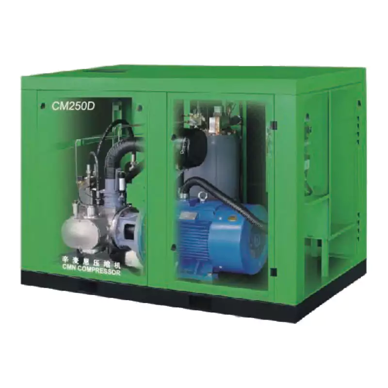
CMD series oil-free compressor — intelligent controller with real-time fault display, operating history log, and remote monitoring capability to support proactive fault management.
When to Stop Troubleshooting and Call a Specialist
Not every fault should be diagnosed in-house. Certain fault conditions require specialist tools, specialist knowledge, or access to internal machine components that should not be disturbed without OEM training and calibrated measurement equipment. Attempting in-house resolution of these faults risks converting a repairable fault into a total air-end replacement event.
🛑
Shut down immediately — call specialist
- High-frequency metallic screech from air-end
- Vibration increasing rapidly during operation
- Rotor-to-rotor contact noise (grinding)
- Smoke or burning smell from motor or controls
- Water leaking from air-end housing area
⚠️
Do not restart — specialist required for diagnosis
- Air-end overload fault recurring after reset
- VSD inverter fault code with output current alarm
- Recurring thermal shutdown despite clean cooler and adequate ventilation
- ISO 8573-1 oil content OOS at annual test — Class A/B pharma circuit
- Phase imbalance fault after supply voltage verified normal
🔧
Schedule specialist service within 5 days
- Specific power risen >8% above baseline
- Dewpoint trending upward despite dryer service
- Progressive discharge temperature rise after cooler cleaning
- Bearing vibration measurement exceeding OEM limit
- VSD cooling fan fault alarm cleared but recurring
Recommended: Built-in Intelligent Diagnostics
1.6 MPa Oil-Free Screw Air Compressor
High-pressure oil-free compressor for demanding applications. Equipped with an intelligent controller providing real-time alarm monitoring, fault history log, performance trending, and remote alarm output — giving your maintenance team visibility of developing faults before they become shutdowns. ISO 8573-1 Class 0 certified for laser cutting, pharmaceutical, and food production environments.
View Product Details →
Frequently Asked Questions
My oil-free compressor keeps tripping on high temperature despite a clean cooler. What should I check?
+
After confirming the cooler is clean, work through this sequence: (1) Measure the actual plant room ambient temperature at the compressor inlet — not at the room thermostat, which may be on the opposite wall. If ambient exceeds 40°C, address ventilation before anything else. (2) Confirm the cooler fan is running at correct speed and direction. (3) Check for hot air recirculation — if the compressor’s hot discharge air is being drawn back into its own inlet due to airflow obstruction, clean cooler will still cause overheating. Install a baffle or extend the hot air exhaust duct if needed. (4) Test the temperature sensor calibration — a drifted sensor may be reporting higher than actual. (5) If all above are normal, schedule an air-end inspection — rotor inefficiency generates excess compression heat that a correctly-functioning cooler cannot fully remove.
System pressure has dropped gradually over 6 months. How do I identify a leak?
+
A gradual pressure drop over months typically indicates either a growing system leak or increasing demand. To differentiate: (1) Perform an overnight leak-down test — pressurise the system to normal working pressure, shut the compressor off, and monitor pressure over 8 hours. More than 0.05 MPa drop indicates a significant leak. (2) For leak location, use an ultrasonic leak detector during production — it detects the ultrasonic signature of escaping compressed air through background noise. Common locations: threaded fittings and push-in connectors (vibration loosens them over time), ball valve stem packing, quick-release couplers (the most common leak source in workshop environments), and flexible hose end fittings. (3) Track compressor load % at the same production volume week-over-week — a load increase without demand increase confirms a growing leak rather than demand growth.
The dryer dewpoint is rising — is this a dryer fault or a compressor fault?
+
Almost always a dryer system issue, not the compressor itself — the compressor simply delivers ambient-humidity air to the dryer; it does not generate moisture beyond normal atmospheric content. Check in this order: (1) Is the dryer in service? Confirm power is on and no fault codes are active on the dryer controller. (2) For refrigerant dryers — check the sight glass for refrigerant bubbles (indicating low charge); measure the temperature difference between inlet and outlet air (should be 15–25°C for a correctly operating refrigerant dryer). (3) Is the dryer’s rated capacity adequate for the actual flow rate? If compressor capacity has been upgraded without upgrading the dryer, the dryer will be overwhelmed. (4) Has inlet air temperature to the dryer increased (hotter summer ambient raising compressor discharge temperature)? Hotter inlet air reduces refrigerant dryer dewpoint performance — a desiccant post-dryer may be needed for extreme summer conditions.
Our annual air test showed oil content above Class 0 but we have an oil-free compressor. How is that possible?
+
This is more common than expected and the cause is almost always atmospheric hydrocarbon contamination at the compressor intake, not machine failure. Vehicle exhaust (forklift propane, diesel delivery trucks), solvent storage areas near the intake, and even seasonal dust with bound hydrocarbon from road surfaces can elevate background atmospheric hydrocarbons to levels that register on ISO 8573-1 test methods. The diagnostic is straightforward: take a background air sample at the compressor intake location using the same test method. If the intake air itself contains elevated hydrocarbons, your compressor is faithfully delivering what it receives — and the solution is to relocate the intake or install an activated carbon pre-filter. If the intake sample is clean but compressor outlet is contaminated, investigate gear oil seals (dry screw) or activated carbon filter condition.
How do I tell if my compressor needs a full overhaul or just a service?
+
A scheduled service (filter changes, bearing grease, gear oil, valve checks) is required at 2,000–4,000 hour intervals regardless of apparent condition. An air-end overhaul is indicated when one or more of these conditions are present: specific power has risen more than 8–10% above the commissioning baseline at the same operating pressure; a thorough vibration analysis has identified sub-acceptable bearing condition; rotor clearance measurement during an open-ended inspection exceeds OEM tolerances; or the machine has accumulated its rated air-end service life (typically 40,000–60,000 hours for water-lubricated designs, 20,000–40,000 for dry screw). Contact
our service team for a performance assessment — we can distinguish a serviceable machine from one approaching overhaul through a combination of performance data review and on-site inspection without full disassembly.
Need a Specialist for a Fault You Can’t Resolve?
Australia Oil Free Air Compressor Co., Ltd. provides on-site fault diagnosis, air-end inspections, and emergency service for oil-free compressor installations across Australia. Don’t let a diagnostic uncertainty become a production shutdown.
Contact Our Service Team
Email: [email protected]
| Contact Us
| About Us