Why Oil-Free Condensate Is Not the Same as Clean Water
A common assumption — and a regulatory pitfall — is that condensate from an oil-free compressed air system can be discharged directly to drain. The reasoning seems logical: no oil in the compressor means no oil in the condensate. This is incorrect, and in many Australian states it is an environmental offence to discharge compressed air condensate to stormwater or sewer without treatment or approval.
Compressed air condensate from any compressor — oil-free or otherwise — is not clean water. The air drawn into the compressor carries atmospheric contaminants: oil vapour from vehicle exhaust and industrial processes (typically 0.01–0.5 mg/m³ in industrial environments), particulate, microorganisms, heavy metals (lead, zinc, copper from traffic and industrial sources), and dissolved gases. When this air is compressed and cooled, these contaminants concentrate in the condensate. A typical oil-free compressed air system operating in an industrial environment produces condensate with a total hydrocarbon content of 50–200 mg/L — well above the discharge limits for most Australian sewer authorities (typically 50 mg/L) and far above stormwater discharge limits (typically 1–10 mg/L).
Additionally, the condensate from refrigerated dryers and desiccant dryers has different contamination profiles. Refrigerated dryer condensate contains the bulk of the moisture removed from the air stream; desiccant dryer condensate (from the regeneration cycle) may also contain trace desiccant fines and higher concentrations of atmospheric hydrocarbons that were adsorbed onto the desiccant during operation.
Where Condensate Forms in an Oil-Free Compressed Air System
Condensate forms at every point in the system where compressed air is cooled below its dew point. Understanding the location and volume of condensate generation at each point is essential for correct drain sizing.
The aftercooler cools compressed air from discharge temperature (typically 40–60°C on a water-lubricated machine; 150–200°C on a dry oil-free screw) to near-ambient temperature. This causes the bulk of the moisture in the air stream to condense. The aftercooler separator or moisture trap immediately downstream is typically the highest-volume condensate point in the system — 60–80% of total condensate generated is collected here.
The receiver provides further thermal equilibration — compressed air that entered the receiver slightly above ambient temperature cools to full ambient as it sits. The resulting condensate collects at the bottom of the receiver. The receiver drain is one of the most frequently neglected drain points — a receiver without a functional drain fills with condensate, which is then carried downstream in slugs when demand spikes.
The refrigerated dryer cools compressed air to its target pressure dew point (typically +2°C to +10°C), causing substantial moisture condensation. The dryer’s internal separator and drain handle the largest single volume of condensate in systems with refrigerated drying. A failed refrigerated dryer drain is the single most common cause of downstream moisture contamination in refrigerated dryer systems.
Coalescing filters and particulate filters collect condensate in their bowls as liquid water and oil aerosol coalesce onto the filter medium. Filter bowl drains must operate correctly for the filter to function — a full filter bowl causes re-entrainment of collected liquid back into the air stream. Filter bowl drains are typically the smallest volume but largest number of drain points in a complex filter train.
In any distribution system that is not perfectly dry (i.e., not desiccant dried to −40°C or better), condensate forms at low points in the distribution pipework — particularly in long horizontal runs and at the bottom of vertical legs. These points require periodic manual drain valves or automatic drain traps to prevent water slugs from reaching tools and processes.
Desiccant dryers regenerate by passing a dry purge air stream through the saturated desiccant bed, desorbing moisture and discharging it as a warm, humid exhaust. For heatless desiccant dryers, this purge is vented to atmosphere and produces no liquid condensate. For heated desiccant dryers with cooled regeneration, the exhaust passes through a cooler and separator that produces a smaller volume of concentrated condensate.
Condensate Volume Estimation
Estimating condensate volume is important for drain sizing, collection tank sizing, and disposal planning. The volume depends on compressor output, inlet air humidity, inlet air temperature, and system pressure. A simplified estimate for planning purposes:
| Compressor Size | Hot Humid Day (RH 80%, 30°C inlet) | Mild Day (RH 60%, 20°C inlet) | Dry Day (RH 40%, 15°C inlet) |
|---|---|---|---|
| 7.5 kW / ~1.0 m³/min FAD | ~25–40 L/day | ~12–18 L/day | ~6–10 L/day |
| 22 kW / ~3.5 m³/min FAD | ~85–130 L/day | ~40–65 L/day | ~20–32 L/day |
| 45 kW / ~7.5 m³/min FAD | ~185–280 L/day | ~85–135 L/day | ~42–65 L/day |
| 132 kW / ~22 m³/min FAD | ~550–800 L/day | ~250–390 L/day | ~120–190 L/day |
Figures assume 8-hour operating day at 7 bar outlet pressure, refrigerated dryer. Australian summer conditions (high humidity, high temperature) produce significantly more condensate than mild-weather operation. Size collection tanks for worst-case conditions.
Drain Types: Selection Guide for Each Application Point
Opens on a timed cycle (e.g., 30 seconds every 30 minutes). Simple, low-cost, reliable. The primary disadvantage is that it releases compressed air with the condensate — wasting energy and creating noise. Also, the timer is set for expected condensate volume; if condensate generation is higher than expected (humid day), the bowl may fill between cycles; if lower, the drain releases compressed air for part of the open period unnecessarily.
Uses a capacitive sensor to detect liquid level in the bowl, opening the drain valve only when liquid is present and closing as soon as the bowl empties — releasing no compressed air with the condensate. More expensive than timer drains but eliminates energy waste and adjusts automatically to variable condensate generation rates. The best solution for high-pressure systems and any drain point where energy efficiency matters.
A ball float rises with condensate level and mechanically opens the drain valve, closing again when the bowl empties. No electrical power required. Reliable in steady-state conditions. Vulnerable to fouling by debris or sludge that prevents the float from seating correctly — causing either continuous air loss (float stuck open) or condensate overflow (float stuck closed). Requires periodic cleaning.
Operator-opened valve at condensate collection points. Reliable when operated but entirely dependent on operator discipline. In practice, manual drains are frequently neglected — the receiver fills with condensate, the aftercooler separator overflows, and moisture carries over into downstream systems causing quality and corrosion problems. Acceptable as a backup or for very low condensate volume points only.
Australian Condensate Disposal Regulations
In Australia, the disposal of compressed air condensate is regulated primarily by state environment protection authorities (EPAs) and local water authorities. The key regulatory framework:
Discharge of condensate (even from oil-free compressors) to stormwater drains is an offence under the Protection of the Environment Operations Act (NSW), the Environment Protection Act (Vic), and equivalent legislation in all states. Stormwater discharges must be substantially free of hydrocarbons — condensate from an industrial compressed air system typically exceeds stormwater quality limits by a factor of 10–100× even from oil-free systems.
Most Australian local water authorities (Sydney Water, Melbourne Water, SA Water, etc.) classify compressed air condensate as trade waste requiring approval before discharge to sewer. Typical sewer discharge limits for hydrocarbons are 50 mg/L total petroleum hydrocarbons. Condensate from oil-free systems may meet this limit without treatment in some cases — but a trade waste agreement must be obtained before discharge begins. Some authorities require a grease trap or oil-water separator before the sewer connection regardless of compressor type.
The fully compliant approaches to compressed air condensate disposal are:
- → Oil-water separator / condensate treatment unit: Dedicated compressed air condensate treatment units use activated carbon and coalescing media to reduce hydrocarbon content to below 15 mg/L, making the treated water suitable for sewer disposal. Available as compact inline units sized for the condensate volume.
- → Containerised collection and licensed disposal: Collect all condensate in a sealed container; arrange disposal by a licensed liquid waste contractor. Correct for any volume but has ongoing cost.
- → Evaporation (arid sites only): In very dry climates and on sites with appropriate evaporation basins, condensate may be directed to an approved evaporation area. EPA approval required.
Designing a Compliant Condensate Collection System
A complete condensate management system for an oil-free compressed air installation should address collection, routing, treatment, and disposal in a single integrated design. The following elements are required for a compliant, low-maintenance system:
Condensate from Water-Lubricated Oil-Free Compressors
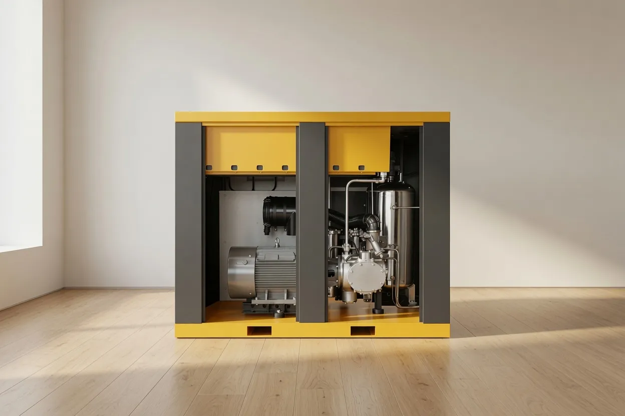
Water-lubricated oil-free screw compressors — including the CM45D and CM132DV — use water as the compression medium and lubricant. The water circuit is separate from the air stream in normal operation, but the system does produce two water-related discharge streams that require management: the water circuit blowdown (periodically discharged to maintain water quality in the circuit) and the normal compressed air condensate from the aftercooler and downstream treatment.
Water circuit blowdown from a water-lubricated compressor is significantly cleaner than condensate from a dry oil-free screw system — because the water circuit contains no oil at all. The water circuit blowdown typically meets municipal water quality limits and can be discharged to sewer as trade waste without treatment in most Australian jurisdictions, subject to obtaining the appropriate trade waste approval from the local water authority. The compressed air condensate from the downstream treatment components (aftercooler separator, dryer, filters) is handled identically to any other oil-free compressed air condensate and follows the disposal pathway described above.
Condensate Management Support from Australia Oil Free Air Compressor
Australia Oil Free Air Compressor Co., Ltd. includes condensate management design in every compressed air system proposal. We specify the correct drain type and size for each collection point, design the collection header, and recommend appropriate condensate treatment or disposal solutions for your site’s condensate volume and local regulatory requirements.
For facilities with existing compressed air systems that have inadequate condensate management — or where drain failures are causing moisture carry-over into processes — our service team assesses the existing drain configuration and recommends upgrades. Replacing failed timer drains with electronic zero-loss units is a common service upgrade that simultaneously resolves moisture carry-over and reduces energy waste from unnecessary air venting.
Contact us at [email protected] for condensate management assessment and design support.
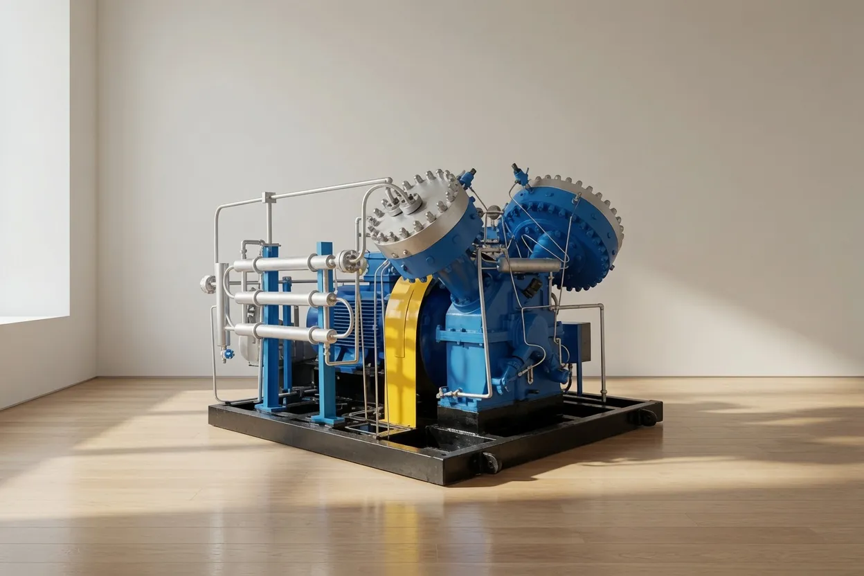
CM45D — Water-Lubricated Oil-Free Screw Compressor: Cleanest Condensate of Any Compressor Design
The CM45D water-lubricated oil-free screw compressor produces the cleanest condensate of any industrial compressor design. Because there is no oil anywhere in the compression system, the aftercooler condensate contains only atmospheric hydrocarbon contamination — not compressor lubricant contamination. In clean industrial environments, CM45D condensate frequently tests below 20 mg/L total hydrocarbons without treatment, compared to 100–300 mg/L for oil-injected compressors with filtration and 50–150 mg/L for dry oil-free screw designs. This significantly simplifies condensate disposal — in many cases, a simple trade waste approval for sewer disposal is sufficient without the need for a dedicated condensate treatment unit.
Frequently Asked Questions
Australia Oil Free Air Compressor Co., Ltd.
Charlton Industrial Area, Australia | [email protected]