CFM Calculation Guide
The complete, worked methodology for calculating compressed air flow requirements in CFM and L/min — covering individual consumer measurement, diversity factors, headroom calculation, and application-specific demand profiles for dental, laboratory, food production, pharmaceutical, and laser cutting facilities.
CFM — cubic feet per minute — is the most common unit for compressed air flow in Australian industrial specifications, appearing on US-manufactured equipment datasheets, dental unit specifications, laboratory instrument requirements, and laser cutting machine manuals. Getting the CFM requirement right is the starting point for selecting the correct oil-free air compressor: too low and the system under-delivers, causing pressure drops that disrupt production, damage pneumatic instruments, and — in regulated industries — trigger compliance events. Too high and capital and energy are wasted. This guide provides a complete, step-by-step methodology for calculating the CFM requirements of an oil-free air compressor installation, covering every application type with worked examples, conversion references, diversity factor guidance, and the practical checks that verify your calculation before you commit to a machine size. Whether you are specifying a new dental practice, a pharmaceutical manufacturing suite, a food production line, or a laser cutting facility, this guide gives you the numbers and the method to get the selection right.
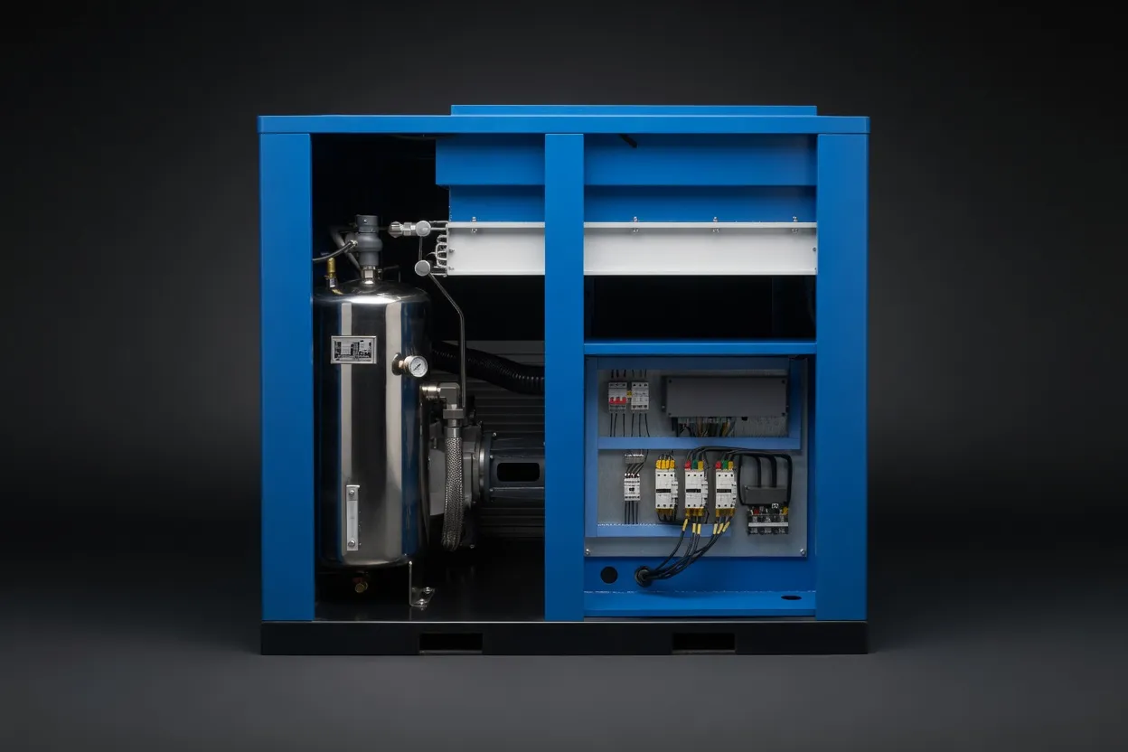
CFM calculation determines the compressor model — too small causes pressure shortfall; too large wastes capital and energy through chronic low-load inefficiency. The method matters.
CFM Fundamentals: What You’re Actually Measuring
CFM stands for cubic feet per minute — a volumetric flow rate. For compressed air, it is always referenced to atmospheric conditions (temperature, pressure, and humidity) — this is called Free Air Delivery (FAD) or SCFM (Standard Cubic Feet per Minute). This distinction is critical: a compressor does not deliver 10 CFM of compressed air at 100 PSI — it delivers 10 CFM of atmospheric air that has been compressed to 100 PSI. At 100 PSI, those 10 CFM of atmospheric air have been physically reduced to approximately 1.18 CFM of volume (because pressure × volume is constant at constant temperature).
Essential Unit Conversions — Keep This as a Reference
1 CFM
= 28.32 L/min
= 0.02832 m³/min
= 1.699 m³/hr
1 L/min
= 0.0353 CFM
= 0.001 m³/min
= 0.06 m³/hr
1 m³/min
= 35.31 CFM
= 1,000 L/min
= 16.67 L/sec
Pressure
1 PSI = 0.0689 bar = 0.006895 MPa
1 bar = 14.5 PSI = 0.1 MPa
1 MPa = 145 PSI = 10 bar
Always use FAD (Free Air Delivery) for sizing calculations. Compressor datasheets may list “displacement” or “swept volume” — which is always higher than FAD. FAD is what the machine actually delivers after accounting for volumetric efficiency losses. Use only ISO 1217 FAD figures when comparing compressor quotations.
The 4-Step CFM Calculation Method
1
List Every Compressed Air Consumer with its CFM Requirement
Create a complete inventory of every device, instrument, tool, and process that uses compressed air. For each, record its air consumption in CFM (or L/min) at its rated operating pressure. Sources for consumption data, in order of preference:
A — Equipment Datasheet (Best)
Find “air consumption,” “air requirement,” or “CFM” in the technical specification. Most dental chairs, lab instruments, and industrial tools specify this. Use the maximum operating consumption, not the idle or average figure.
B — Direct Flow Measurement
Install a temporary flow meter in the supply line to the consumer and log the maximum instantaneous flow during normal operation. Most accurate method — eliminates guesswork. Portable clamp-on flow meters available for hire from industrial suppliers.
C — Industry Reference Tables
Use published air consumption guides for standard tool types where datasheet data is unavailable. Reference tables at the end of this article cover the most common consumer types in dental, laboratory, food, and industrial applications.
Important: Record consumption at the consumer’s required pressure, not at the compressor delivery pressure. A tool that requires 80 PSI inlet pressure and consumes 2 CFM at 80 PSI will consume more CFM if supplied at 100 PSI due to the higher pressure driving a larger mass flow through the same orifice — factor this in for tools with significant orifice-controlled flow.
2
Calculate Peak Simultaneous Demand & Apply Diversity Factor
Sum the CFM of all consumers that could operate simultaneously at maximum consumption — this is your raw peak simultaneous demand. Then apply a diversity factor to account for the reality that not every consumer runs at maximum consumption simultaneously.
| Application Type |
Recommended Diversity Factor |
Rationale |
| Dental practice (multi-chair) |
1.00 |
All chairs active simultaneously at peak; no diversity — design for full simultaneous use |
| Pharmaceutical manufacturing |
0.90–0.95 |
Batch operations have high process utilisation; near-simultaneous peak common |
| Food production line |
0.80–0.90 |
Conveyor/actuator operation is continuous but not always at maximum instantaneous draw |
| Multi-lab research facility |
0.70–0.80 |
Not all instruments run simultaneously; significant variation in lab scheduling |
| General industrial workshop |
0.65–0.80 |
Tool-based intermittent use; rarely all tools active simultaneously |
| Single-purpose continuous process (laser cutting, PET blowing) |
1.00 |
Single consumer runs continuously at full demand — no diversity applies |
Worked Example — Food Production Facility
Packaging machine A: 4.2 CFM
Packaging machine B: 4.2 CFM
Conveyor actuators (8 × 0.4): 3.2 CFM
Spray nozzle station: 5.8 CFM
Instrument air (6 points × 0.3): 1.8 CFM
Compressed air cleaning gun: 2.0 CFM
Raw peak: 4.2+4.2+3.2+5.8+1.8+2.0 = 21.2 CFM
× Diversity factor 0.85: 21.2 × 0.85 = 18.0 CFM design demand
3
Add Headroom for Leaks, Growth, and Compliance Buffer
Your design demand figure covers current consumption by identified consumers. The compressor’s rated FAD must exceed this by a headroom margin that accounts for:
System Leaks (+10%)
Every compressed air system develops leaks over time. Allow 10% of design demand for system leakage in a new installation (growing to 25% without active leak management).
Future Growth (+5–10%)
New equipment additions, additional production lines, or expanded operations will increase demand. A 5–10% growth buffer avoids the need to upsize the compressor within the first 3–5 years.
Regulated Buffer (+10%) — Pharma/Food
TGA GMP and BRCGS facilities should add 10% for validation testing airflow and N+1 redundancy planning — compressor FAD should be sized so that the facility can continue operating on one unit if the second is in service.
Continuing the Food Production Example:
Design demand: 18.0 CFM
+ 10% system leaks: 18.0 × 1.10 = 19.8 CFM
+ 10% regulated/growth buffer: 19.8 × 1.10 = 21.8 CFM minimum compressor FAD
→ Select compressor rated at ≥ 23 CFM FAD at 0.8 MPa (next standard model above 21.8)
4
Verify Against Available Compressor Models & Confirm at Rated Pressure
Compressor FAD is rated at a specific delivery pressure. A compressor rated at 25 CFM at 0.8 MPa (116 PSI) will deliver less FAD at 1.0 MPa and more at 0.6 MPa. Always confirm the FAD at your system’s required working pressure — not at an adjacent standard pressure rating. Request the full pressure-FAD performance curve from the supplier. Key verification checks:
✓
FAD at rated pressure matches or exceeds your minimum CFM: Compare the model’s ISO 1217 FAD at your delivery pressure to your calculated minimum. Add 5–10% rounding margin — if your minimum is 21.8 CFM and the model delivers 22 CFM, specify the next model up (e.g., 25 CFM).
✓
Duty cycle is rated for your operating hours: If you need 24/7 continuous operation, the compressor must be rated for 100% duty cycle. Piston compressors rated for 50–70% duty cannot run continuously — only oil-free screw compressors provide 100% continuous duty rating.
✓
The average load factor will be in the efficient range: Ideally 60–85% average load. If the selected compressor will run at 90%+ average load, size up by one model. If it will run at less than 50% average load, size down or choose a VSD to maintain efficiency.
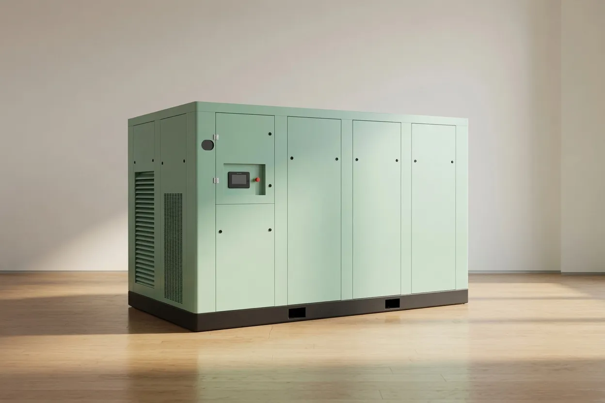
Oil-free screw compressor correctly sized to design demand — running at 65–75% average load delivers optimal specific power, service life, and energy efficiency.
CFM Reference Tables by Application
The following tables provide typical air consumption figures for the most common compressed air consumers in Australian dental, laboratory, food production, pharmaceutical, and laser cutting applications. Use these as estimates where equipment datasheets are not available — then confirm with direct measurement wherever possible.
Dental Practice
| Consumer |
CFM per unit |
L/min per unit |
Min Pressure (PSI) |
| Turbine air handpiece |
1.6–2.4 |
45–68 |
55–75 |
| 3-in-1 syringe (air/water) |
0.4–0.6 |
11–17 |
55–75 |
| Electric handpiece + 3-in-1 |
0.5–1.0 |
14–28 |
55–75 |
| Implant / surgical unit (per room) |
2.8–4.2 |
80–120 |
70–90 |
Dental sizing rule of thumb: For a turbine handpiece practice, budget
2.1 CFM (60 L/min) per chair + diversity factor 1.0. A 4-chair practice needs ≥8.4 CFM FAD × 1.15 headroom =
≥ 9.7 CFM → select a 10–12 CFM model. See our
CM45D for small-practice applications scaling to dental clinic requirements.
Laser Cutting (Fibre Laser)
| Laser Power / Material |
CFM Required |
L/min Required |
Delivery Pressure |
Recommended |
| 3–6 kW, mild/SS <6mm |
28–42 |
800–1,200 |
232 PSI (1.6 MPa) |
1.6MPa Oil-Free |
| 6–12 kW, SS/aluminium <12mm |
42–71 |
1,200–2,000 |
290–435 PSI (2.0–3.0 MPa) |
3.0MPa 2-Stage |
| 12–20 kW, thick plate >12mm |
71–141 |
2,000–4,000 |
435+ PSI (3.0+ MPa) |
CM242GPV |
Food Production — Typical Consumers
| Consumer |
CFM |
L/min |
Notes |
| Pneumatic packaging machine (per machine) |
3.5–8.5 |
100–240 |
Verify with manufacturer; varies greatly by machine type |
| Double-acting pneumatic actuator (per actuator) |
0.1–0.5 |
3–14 |
Depends on cylinder bore and stroke frequency |
| Pneumatic conveyor (per section) |
1.5–4.2 |
42–120 |
Dilute-phase conveying at lowest end; dense-phase higher |
| Air jet cleaning nozzle (per nozzle) |
0.5–2.0 |
14–57 |
Highly dependent on nozzle design and pressure; measure where possible |
| Instrument air (per control point) |
0.15–0.5 |
4–14 |
Low consumption but needs clean dry air; include in all regulated facility calculations |
| Air spray coating / glazing (per gun) |
4.2–7.1 |
120–200 |
High consumption; include in peak demand calculation; diversity factor may apply if intermittent |
Pharmaceutical Manufacturing
| Process |
CFM |
L/min |
Air Class |
| Tablet coating pan (per pan) |
5.3–12.4 |
150–350 |
Class B (ISO 1.2.0) |
| Fluid bed dryer (per unit) |
7.1–17.6 |
200–500 |
Class B (ISO 1.2.0) |
| Aseptic filling line purge |
1.8–5.3 |
50–150 |
Class A (ISO 1.2.0) |
| Suite pneumatic actuators (per suite) |
3.5–10.6 |
100–300 |
Class C (ISO 1.4.1) |
Free CFM Calculation Service
Tell Us Your Consumers — We’ll Calculate Your CFM
Send us your list of compressed air consumers (equipment type, quantity, operating schedule) and your required delivery pressure. Our team calculates your design demand CFM, applies the correct diversity factor for your application type, and recommends the appropriate model from our CM45D, CM132DV, and CM242GPV range. No obligation.
Request Free CFM Calculation →
Frequently Asked Questions
What’s the difference between CFM, SCFM, and ACFM?
+
All three measure volumetric airflow in cubic feet per minute, but at different reference conditions. CFM (cubic feet per minute) in compressed air contexts almost always means free air delivery at atmospheric conditions — essentially the same as SCFM in most practical sizing scenarios. SCFM (standard cubic feet per minute) references air at exactly 14.696 PSI, 60°F (15.6°C), and 0% relative humidity — the US standard reference condition. ACFM (actual cubic feet per minute) references air at the actual local conditions at the measurement point — useful for accounting for altitude and temperature effects on density. For most Australian industrial sizing purposes, treat CFM and SCFM as equivalent. When a compressor datasheet lists FAD in CFM, it is referencing ISO 1217 conditions (1 bar, 20°C, 0% relative humidity) — very close to SCFM but not exactly identical. The difference is less than 2% and immaterial for compressor sizing decisions.
My dental unit manufacturer says it needs “80 PSI at 2 CFM.” How do I use this for compressor sizing?
+
This specification means the dental unit requires 2 CFM of free air delivered at a minimum of 80 PSI at the unit’s air inlet. For compressor sizing: (1) Use 2 CFM as the air consumption per dental unit in your consumer list. (2) Use 80 PSI as the minimum required pressure at the dental unit inlet. Add your distribution pressure drop (typically 0.05–0.10 MPa / 7–15 PSI) to determine the minimum compressor delivery pressure: 80 + 10 = 90 PSI minimum compressor setpoint. For a two-chair practice with 2 turbine handpiece units: 2 × 2.0 CFM = 4.0 CFM × diversity 1.0 × 1.15 headroom = 4.6 CFM minimum FAD at 90 PSI (0.62 MPa) — select a compressor rated at ≥5 CFM at 0.7 MPa or above.
How do I calculate CFM if I don’t know the consumption of each piece of equipment?
+
Three approaches when datasheet data is unavailable: (1) Empirical measurement on existing system: If you are expanding an existing installation, fit a temporary calibrated flow meter (hire from industrial suppliers, AUD 200–500/week) in the main supply header and log peak flow during normal production over 5–10 days. The measured peak flow is your current design demand baseline — add the consumption of new equipment to this measured baseline. (2) Compressor controller data: If you have an existing compressor with a controller, read the load % display during peak production. Multiply rated FAD × load% to get approximate current demand. (3) Orifice method for simple consumers: For tools with a known orifice (e.g., an air cleaning gun), CFM can be estimated from the orifice area and supply pressure using the compressible flow orifice equation — available in engineering reference tables. For regulated industry applications where sizing precision matters for compliance, direct measurement is always preferred over estimation.
Does a laser cutting machine’s CFM requirement change with the material being cut?
+
Yes, significantly. Laser cutting air consumption depends on three variables that change with material and application: (1) Nozzle pressure: thicker material and higher laser power requires higher nozzle pressure, which consumes more mass flow at the same volumetric flow rate — effectively requiring higher compressor FAD; (2) Nozzle diameter: different cutting modes use different nozzle sizes, affecting orifice flow; (3) Cutting vs. piercing: the piercing phase (initial hole entry) requires maximum pressure and flow — this is the peak demand event that sizes the compressor, not the steady cutting speed demand. Always specify your laser cutting compressor based on the highest-pressure piercing demand for the thickest material you will cut, at the nozzle diameter your machine uses for that operation. Laser machine manufacturers typically provide a “compressor requirements” table in the machine documentation — use this as your primary reference rather than general estimates.
How much CFM does an average pharmaceutical tablet coating pan require?
+
A pharmaceutical tablet coating pan uses compressed air for three functions, each with different flow requirements: (1) Spray gun atomisation air — 1.5–3.5 CFM (42–100 L/min) per gun at 15–25 PSI (0.10–0.17 MPa), depending on the spray gun design and coating formulation viscosity; (2) Inlet drying air — the largest consumer at 3.5–10.6 CFM (100–300 L/min) at 3–7 PSI (0.02–0.05 MPa), used to carry moisture out of the coating chamber; (3) Exhaust fan drive air — 0.4–1.4 CFM (12–40 L/min) if the exhaust fan is air-driven. Total per coating pan: typically 5–12 CFM at the pan inlet manifold, at 0.5–0.7 MPa system pressure. Always request the process air specification from the coating pan manufacturer — it varies significantly between perforated and solid drum designs and between batch sizes (e.g., 60 L drum vs. 600 L production drum). For multi-suite pharmaceutical plants, the combined coating pan demand is often the dominant consumer in the compressed air balance.
Get the Right CFM — Sized Correctly for Your Application
Australia Oil Free Air Compressor Co., Ltd. provides free, site-specific CFM calculations for dental, pharmaceutical, food, laboratory, and laser cutting applications across Australia — giving you the correct model selection with confidence before you commit to purchase.
Request Free CFM Calculation
Email: [email protected] | Contact Us | About Us