
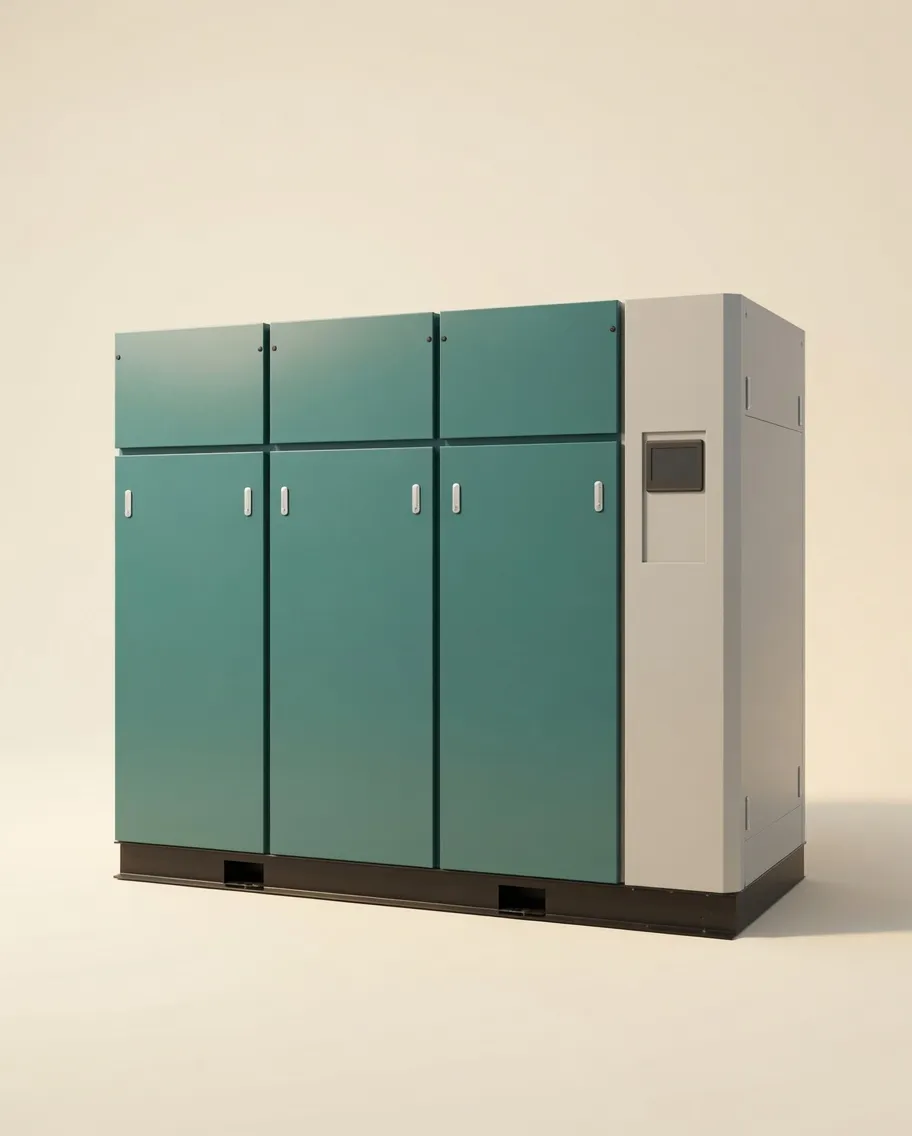
What CFM Actually Means for an Oil-Free Compressor
CFM — Cubic Feet per Minute — measures the volume of air a compressor delivers. For oil-free air compressors, the relevant figure is always FAD (Free Air Delivery): the volume measured at atmospheric pressure, not at discharge pressure. This distinction matters because a machine delivering 100 CFM of air at 100 PSI is actually compressing significantly more atmospheric air to achieve that output.
You will also encounter SCFM (Standard Cubic Feet per Minute) in North American specifications — this refers to airflow corrected to defined standard conditions: 14.696 psia, 68°F (20°C), and 0% relative humidity. In Australian industrial specifications, FAD at ISO 1217 test conditions (ambient 20°C, intake pressure 1 bar absolute) is the standard reference. For practical sizing purposes the two figures are within 2–4% of each other, but always confirm which standard a manufacturer is quoting before comparing units.
A common source of confusion: compressor catalogues often list displacement CFM or theoretical output, which is the physical swept volume of the compression element. Actual FAD is typically 80–95% of displacement for a modern oil-free rotary screw compressor — the difference accounting for volumetric efficiency, valve losses, and temperature effects on intake air density.
The 5-Component CFM Demand Formula
Accurate CFM demand is not a single figure — it is the sum of five distinct components. Missing any one of them is a sizing error that compounds over the equipment lifetime.
Process Demand CFM
The rated consumption of every air-using device at its operating pressure. Sum all devices that may run concurrently. This is your baseline — never the final number.
Leakage Allowance
Compressed air leaks are universal in any piped system. A new, well-maintained system typically leaks 5–10% of total demand. Older systems without recent audit: 20–30%. Always budget for leakage.
Dryer & Filter Purge
Desiccant air dryers consume 10–15% of compressor output for purge air. Refrigerated dryers: negligible. Compressed air filters: 0.5–1% pressure drop but minimal flow loss. Factor this into your demand total.
Peak Demand Spike
Many processes have burst demands 1.5–2× average flow — a pneumatic press cycle, a purge valve opening, or simultaneous tool startup. Peak demand must be met without pressure sag below the minimum process PSI.
Future Growth Reserve
A prudent 15–20% reserve for capacity additions within a 3-year planning horizon prevents costly compressor replacements as production scales. This is not waste — it is insurance against short-cycling new equipment at design-load.
Typical values: Simultaneity 0.75 · Leakage 10% · Desiccant purge 12% · Peak factor 1.15 · Growth 1.20
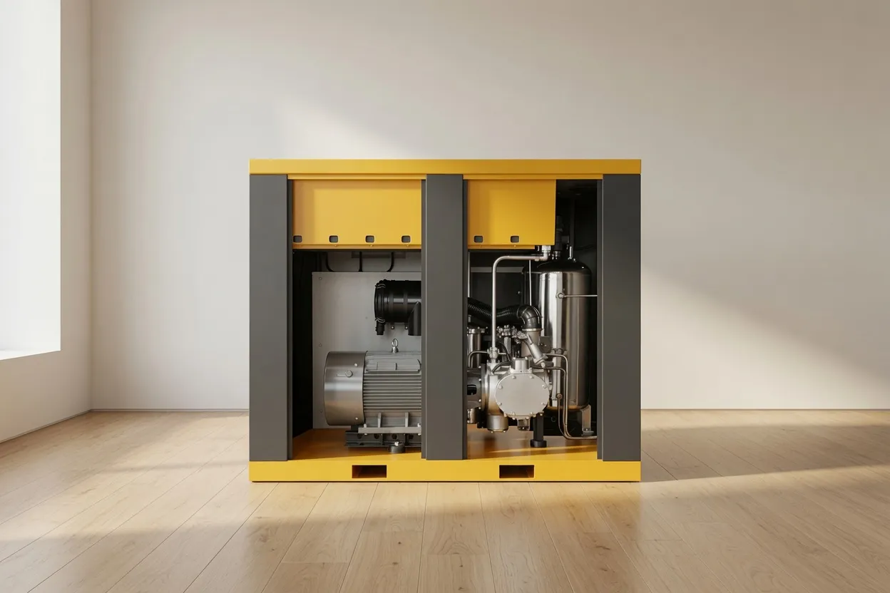
Worked Example: Food Packaging Line
A food packaging facility in Melbourne operates the following equipment simultaneously during peak production. All air must be oil-free compressed air to meet food-grade standards. Here is how the demand calculation works from first principles:
| Equipment | Qty | Unit CFM | Duty Cycle | Effective CFM |
|---|---|---|---|---|
| Pneumatic filling valves | 8 | 4.5 | 80% | 28.8 |
| Rotary indexing actuators | 4 | 2.0 | 60% | 4.8 |
| Air knives (product drying) | 2 | 18.0 | 100% | 36.0 |
| Label applicator pneumatics | 3 | 3.0 | 70% | 6.3 |
| Blow-off nozzles (cleaning) | 6 | 2.5 | 40% | 6.0 |
| Total Process CFM | 81.9 | |||
+ Leakage (10%): + 8.2 → Subtotal: 90.1 CFM
+ Desiccant dryer purge (12%): + 9.8 → Subtotal: 99.9 CFM
× Peak factor (1.15): × 1.15 → Subtotal: 114.9 CFM
× Growth reserve (1.20): × 1.20 → Required FAD: 137.9 CFM
Result: this facility should specify a compressor with a rated FAD of 140–150 CFM at operating pressure. A fixed-speed oil-free rotary screw at 145 CFM FAD would be an appropriate selection.
CFM Reference Benchmarks by Industry
While every installation is unique, these benchmarks from Australian and international industrial installations provide a reliable starting point for preliminary sizing. All figures represent oilless air compressor configurations with oil-free compressed air delivery — no downstream filtration correction is needed for these figures.
How Compressed Air Leaks Inflate Your True CFM Requirement
Compressed air leaks are the most underestimated variable in any sizing project. According to the US Department of Energy, the average industrial facility leaks 20–30% of total compressed air production. In Australian manufacturing, audits conducted across multiple sectors have found consistent leakage rates of 15–25% even in maintained systems.
A 3 mm diameter leak at 100 PSI wastes approximately 25 CFM — equivalent to running a medium pneumatic grinder continuously for no productive purpose. At Australian industrial electricity rates of approximately $0.14–0.18/kWh, this single leak costs an estimated AUD $4,500–6,500 per year in wasted compressor energy.
Leakage Rate by System Age & Condition
| System Condition | Typical Leak Rate | CFM Lost (100 CFM system) | Annual Energy Cost Est. |
|---|---|---|---|
| New installation, well-maintained | 3–5% | 3–5 CFM | AUD $600–1,000 |
| 1–3 years, regular maintenance | 8–12% | 8–12 CFM | AUD $1,600–2,400 |
| 3–7 years, irregular maintenance | 18–25% | 18–25 CFM | AUD $3,600–5,000 |
| 7+ years, no audit performed | 30–40% | 30–40 CFM | AUD $6,000–8,000+ |
Always budget a minimum 10% leakage allowance in any new sizing exercise. For retrofits or expansions of existing systems, commission an ultrasonic leak audit before finalising compressor specifications — the data frequently changes the required FAD by 15–20%.
Why Air Compressor Horsepower Is a Poor Proxy for CFM
A persistent industry misconception is that air compressor horsepower is an adequate proxy for CFM delivery. This is only true within a narrow pressure band. As discharge pressure increases, a fixed HP drive delivers substantially fewer CFM — the relationship is not linear. Consider a 30 HP oil-free rotary screw compressor:
| Operating Pressure (PSI) | Approx. FAD (CFM) | Specific Power (kW/100 CFM) |
|---|---|---|
| 90 PSI | 135–145 CFM | 14–16 kW |
| 115 PSI | 115–125 CFM | 16–18 kW |
| 145 PSI | 95–110 CFM | 18–21 kW |
| 200 PSI | 70–85 CFM | 22–26 kW |
This is why a reputable supplier will always specify both HP and FAD at a defined pressure. Sizing by HP alone, without pressure context, is a specification error. When comparing offerings from multiple suppliers, always insist on FAD figures tested at your actual operating pressure.
How VSD Technology Changes Your CFM Calculation
A variable speed drive compressor (VSD) does not simply match rated CFM to demand — it modulates output continuously between a minimum and maximum speed. This has an important implication for sizing: you must specify both the minimum and maximum CFM range your demand will require, not just the peak figure.
If a VSD compressor is sized only for peak demand, it may spend most of its operational time at or near its minimum speed, where efficiency drops and condensation risk inside the compression element increases. A properly specified VSD unit should operate at 60–90% of its maximum rated speed for the majority of its running hours. For demand ranges below 40% of peak, a second smaller fixed-speed unit often makes more economic sense than a single oversized VSD.
Precision CFM Sizing Support from Our Engineering Team
At Australia Oil Free Air Compressor Co., Ltd., CFM sizing is not a catalogue exercise — it is a structured engineering process. Our team at the Charlton Industrial Area facility works through demand analysis, leakage budgets, pressure drop calculations, and VSD feasibility assessments before recommending a model. We work with real site data, not assumptions.
Our oil free air compressor range has been matched to applications from single-chair dental practices at 2 CFM to large-scale food processing lines at 400+ CFM, all with full air quality documentation and Australian compliance traceability. Every recommendation includes projected energy consumption and total cost of ownership over 5 and 10-year horizons.
Contact us at [email protected] or visit our About Us page to learn more about our process.
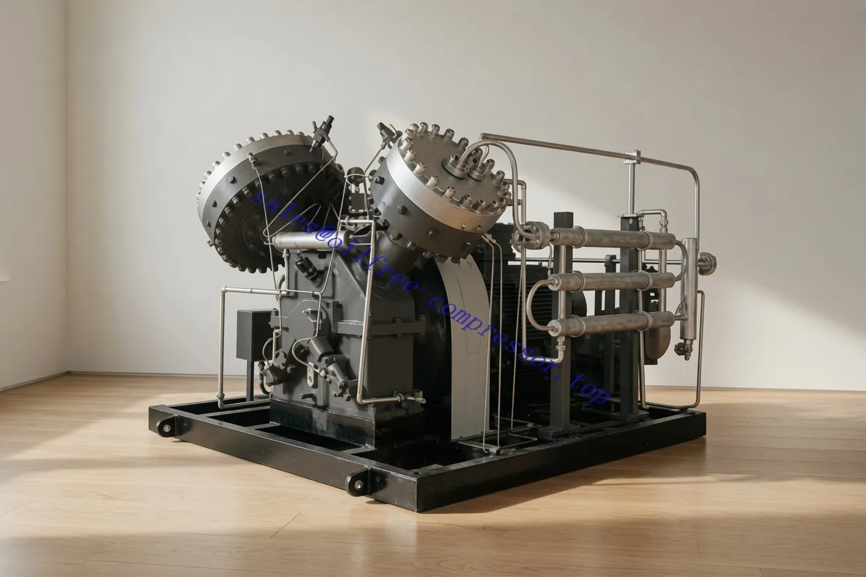
CM132DV Low-Pressure Oil-Free Screw Air Compressor (Water Lubrication)
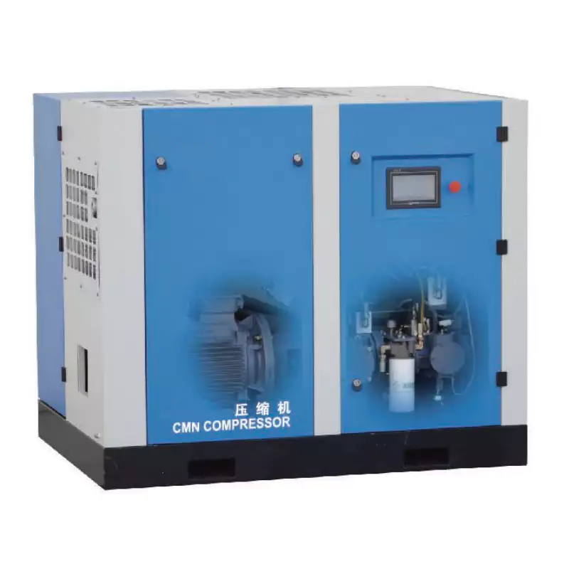
The CM132DV is engineered for applications where high CFM delivery, zero oil carryover, and continuous-duty operation are all simultaneously required. Water lubrication eliminates the risk of PTFE contamination and provides natural cooling, allowing stable FAD output across extended production runs — making it an ideal candidate for food, pharmaceutical, and electronics facilities in the 120–400 CFM range.
Frequently Asked Questions
Australia Oil Free Air Compressor Co., Ltd.
Charlton Industrial Area, Australia | [email protected]