
What the Receiver Tank Actually Does
The air receiver tank in a compressed air system is not merely a storage vessel. It performs at least four distinct functions that directly affect system performance, compressor longevity, and air quality. Understanding all four explains why tank sizing deserves the same engineering attention as the compressor itself — and why the common approach of simply matching a tank to whatever size “came with the compressor” so frequently leads to operational problems.
Stores compressed air during low-demand periods and releases it during demand spikes, preventing pressure sag when multiple tools activate simultaneously. Without adequate buffer volume, peak demand draws down system pressure faster than the compressor can replenish it.
Extends the time between compressor on-cycles, protecting piston and scroll compressors from the thermal and mechanical stress of frequent starts. Each motor start on a fixed-speed unit generates a current inrush of 6–8× running current — frequent starts accelerate motor winding degradation.
As compressed air cools in the receiver, moisture condenses and settles at the tank bottom, reducing the load on downstream dryers and filters. A correctly sized receiver with automatic drain can remove 50–70% of condensate before the air even reaches the dryer — meaningfully extending dryer service intervals.
Provides a brief continuity of supply during a compressor trip, planned maintenance switchover, or filter change — giving operators time to complete an in-progress cycle without shutting down the production line. Most industrial facilities size for 30–60 seconds of emergency supply at normal demand.
For oil free compressor systems — particularly those supplying food, pharmaceutical, or medical applications where air quality certification is critical — the receiver also provides a stable sampling point for in-line air quality monitoring. A fluctuating, undersized receiver makes accurate continuous monitoring difficult, as pressure swings alter the effective concentration readings of oil vapour and particle sensors.
The Engineering Formula for Receiver Tank Sizing
The standard engineering formula for receiver sizing derives from first principles of ideal gas compression and the pressure-volume relationship. It calculates the minimum vessel volume needed to sustain system pressure above a defined minimum for a specified period when compressor output falls short of demand — the classic peak-demand scenario.
V = receiver volume (cubic feet or gallons) · T = acceptable pressure decay time (minutes)
C = compressor output (CFM) · D = demand (CFM) · Patm = 14.7 psia
P1 = initial system pressure (psia) · P2 = minimum acceptable pressure (psia)
Worked Example
A manufacturing facility experiences a peak demand of 120 CFM for up to 3 minutes during each production cycle. The oil-free air compressor is rated at 100 CFM FAD — so during peak demand, there is a 20 CFM shortfall. The system pressure must remain above 95 PSI (109.7 psia) from a starting point of 115 PSI (129.7 psia).
V = 3 × 20 × 14.7 ÷ 20
V = 882 ÷ 20 = 44.1 cubic feet ≈ 330 gallons
So this facility needs a minimum 330-gallon receiver to sustain adequate pressure through a 3-minute peak demand period without the compressor being oversized for average load. Adding 20% safety margin suggests a 400-gallon tank as the specified size.
Practical Rules of Thumb for Common Applications
When a detailed engineering calculation is not practical during initial planning, these industry-proven rules of thumb provide reliable starting points. They are derived from decades of installation experience across Australian and international industrial markets and incorporate reasonable allowances for the peak demand, short-cycle protection, and moisture separation functions described above.
| Application Type | Rule of Thumb | Example: 100 CFM compressor | Rationale |
|---|---|---|---|
| Continuous process (stable demand) | 0.5–1 gal/CFM | 50–100 gal | Low demand variation; buffer mainly for pressure stability |
| General manufacturing (moderate variation) | 1–2 gal/CFM | 100–200 gal | Standard industrial benchmark; covers short-cycle protection |
| Intermittent / pulsating demand | 3–5 gal/CFM | 300–500 gal | Large burst demands (blast cleaning, PET pre-blow, press cycles) |
| VSD compressor system | 0.5 gal/CFM | 50 gal | VSD modulates continuously; large receiver causes hunting at low loads |
| Piston compressor (duty cycle management) | 2–4 gal/CFM | 200–400 gal | Larger tank extends off-cycles, reducing duty fraction and thermal load |
| High-pressure system (200+ PSI) | 1–1.5 gal/CFM | 100–150 gal | Higher pressure differential means stored energy per gallon is greater; less volume needed for same buffer |
Note the VSD entry: a variable speed drive compressor actually benefits from a smaller receiver than a fixed-speed equivalent. This counterintuitive result arises because VSD control logic uses the receiver pressure signal to modulate speed — a very large receiver creates a slow pressure response signal, causing the VSD controller to under-respond to demand changes and overshoot in speed. The optimal receiver for a VSD system is sized for moisture separation and emergency reserve, not for peak demand buffering that the VSD motor speed handles directly.
Primary vs Secondary Receiver Tanks: When to Use Both
Large industrial compressed air systems often use two receiver tanks in series: a primary (wet) receiver positioned immediately after the compressor and before the dryer/filter train, and a secondary (dry) receiver positioned after the dryer, close to the point of use. Understanding the distinct function of each helps optimise the size of both.
The total receiver volume (primary + secondary) should meet or exceed the sizing calculated by the engineering formula for your demand profile. The primary/secondary split is a matter of system layout and dryer protection — not a substitute for adequate total volume.
How Compressor Type Changes Tank Sizing Logic
The right receiver size is not independent of compressor technology. The control mode of the compressor determines how the system interacts with the receiver, and getting this interaction wrong is a common source of both energy waste and premature compressor wear.
The piston compressor starts and stops based on pressure switch trips. A larger receiver means the pressure takes longer to decay from cut-out to cut-in pressure — fewer starts per hour, longer rest periods, lower duty cycle fraction. Recommendation: use the largest receiver the space and budget allow, up to about 4× the compressor’s per-minute output. Beyond that, the benefit of additional volume diminishes.
Similar logic to piston, but scroll units tolerate higher duty cycles. A moderately sized receiver (1–2 gal/CFM) balances short-cycle protection with acceptable floor-space footprint. Very large receivers on scroll compressors can cause the machine to run fewer but longer cycles, which concentrates thermal load — for scroll units, consistent short cycles with adequate cool-down are often preferable to infrequent very long cycles at high duty.
Rotary screw compressors in load/unload control benefit from receivers sized to keep the machine loaded for at least 20–30 minutes per cycle. Frequent short cycles on a screw unit are less harmful than on a piston (no PTFE rings to overheat) but still consume excess energy through repeated unloaded running. Standard benchmark: 1–2 gal/CFM. In modulating control mode, receiver size has less impact on machine longevity.
As noted above, VSD compressors need smaller receivers because speed modulation handles demand variation continuously. An oversized receiver with a VSD unit causes the motor to slow to minimum speed while pressure builds slowly in the large vessel — triggering the VSD to cycle off and restart when a demand spike exhausts the receiver faster than minimum-speed delivery can replenish. A 0.5 gal/CFM receiver is typically ideal for VSD-controlled systems.
Receiver Tank Materials, Standards & Maintenance Requirements
Receiver tanks are pressure vessels and are subject to statutory safety requirements in all Australian states under the Australian Standard AS 1210 for pressure vessels and associated inspection regimes under Work Health and Safety regulations. Selecting a compliant, correctly rated tank is not optional — it is a legal requirement.
In Australia, pressure vessels above 10 kPa and 1 litre in volume must be registered with the relevant state authority if they exceed specific design pressure × volume thresholds. Most industrial compressed air receivers exceed these thresholds. Ensure your receiver tank has an Australian Design Registration (ADR) number and a current inspection certificate before commissioning. Unregistered pressure vessels in industrial service carry significant liability exposure under WHS legislation.
How Compressed Air Leaks Erode Your Effective Tank Capacity
Compressed air leaks affect receiver performance in a way that is rarely discussed but highly significant. A leak is a constant uncontrolled demand that empties the receiver at a rate determined by the leak rate, regardless of production demand. This reduces the effective stored volume available for genuine peak demand buffering and can cause a correctly sized receiver to behave as though it is undersized.
Consider a 200-gallon receiver with 30% system leakage. Instead of a 100 CFM compressor versus a 120 CFM peak demand (20 CFM net shortfall to be covered by the tank), the actual picture is: 100 CFM compressor versus 120 CFM demand plus 30 CFM leakage = 50 CFM net shortfall. The receiver that was sized for a 20 CFM shortfall is now being asked to cover a 50 CFM shortfall — it will be exhausted 2.5× faster than the design calculation predicted.
Fix leaks before resizing receivers. A 30% leakage rate means 30% of your compressor output, receiver volume, and dryer capacity is being used non-productively. Repairing leaks typically costs AUD $200–800 per leak point in labour and fittings — returning 5–20 CFM of productive capacity at a fraction of the cost of purchasing additional compressor or tank capacity to compensate.
Complete System Design — Not Just the Compressor
Australia Oil Free Air Compressor Co., Ltd. approaches every project as a system design exercise, not a compressor sale. That means the receiver tank specification is part of every proposal we provide — sized by engineering calculation for your actual demand profile, compressor control mode, and application requirements. We supply both carbon steel and stainless steel AS 1210-compliant receivers across the full capacity range, and our quotations include ADR-registered units where required by state regulations.
Whether you are specifying a new system from scratch or replacing an undersized tank on an existing installation, our team at Charlton Industrial Area, Australia can provide a fully documented tank sizing justification alongside the compressor proposal. We also offer compressed air leak detection service referrals to help customers establish accurate demand baselines before specification.
Contact us at [email protected] to discuss your tank sizing requirements alongside the oil-free rotary screw compressor or other unit under consideration.

CM110G — Air Compressor for PET Bottle Blowing
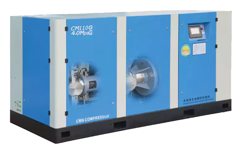
The CM110G is engineered specifically for the most tank-demanding application in the beverage industry: PET bottle blowing. This application generates extreme peak demands with rapid pressure swings — exactly the scenario where receiver tank sizing is most critical. The CM110G is designed with integrated receiver tank specifications as part of its system proposal, ensuring the compressor and vessel are matched from the outset. If your facility runs PET blow moulding and you have ever experienced pressure drop during the blow cycle, inadequate receiver volume is almost certainly a contributing factor.
Frequently Asked Questions
Australia Oil Free Air Compressor Co., Ltd.
Charlton Industrial Area, Australia | [email protected]