
The Ventilation Problem: Why Compressor Rooms Get So Hot
A compressor room is fundamentally a heat source — not just a machine location. Every kilowatt of electrical energy consumed by an oil free compressor becomes heat within the compression element, motor windings, and drive electronics. In a 45 kW compressor, approximately 38–42 kW of that input is converted to heat that must be continuously removed from the room. This is not a design flaw — it is the physics of compression — but it demands a ventilation system that treats the heat load as a first-class design parameter, not an afterthought.
The consequences of inadequate ventilation compound rapidly. As room temperature rises, the compressor’s cooling air becomes less effective — a hot cooling medium removes less heat per unit volume than cool air. This causes discharge temperature to rise, increasing thermal stress on the compression element, accelerating lubricant degradation in bearing circuits, and eventually triggering the overtemperature protection relay — halting production.
In Australian summer conditions across major industrial regions — temperatures of 38–42°C are routine in Western Australia, Queensland, Northern Territory, and inland NSW and Victoria — inadequate ventilation design is not a theoretical risk. It is a guaranteed operational failure in the hottest weeks of the year, precisely when production pressure is highest and the cost of downtime is greatest.
Understanding the Room Heat Load: All Sources, Not Just the Compressor
The ventilation system must handle the total heat load in the compressor room — not just the compressor’s heat output. In a typical installation, several additional heat sources contribute to the thermal balance and must be included in the ventilation calculation:
| Heat Source | Typical Contribution | Notes |
|---|---|---|
| Compressor motor & element | 85–94% of motor kW | Primary heat source; use manufacturer’s stated heat rejection figure, not a percentage estimate |
| Air dryer (refrigerated) | 0.5–2.0 kW | Refrigeration condenser rejects heat to room; check dryer technical data |
| Hot pipework radiation | 0.1–0.5 kW per 10m | Uninsulated hot pipe radiates to room; insulate all compressed air pipework in the compressor room |
| Solar gain (roof/walls) | 5–30 kW (room-dependent) | Critical in Australian summer — uninsulated metal buildings can add 15–25 kW solar heat load; insulate roof and west-facing walls |
| Lighting & other equipment | 0.2–1.0 kW | Minor but should be included for accuracy in tight thermal budgets |
The solar gain entry is particularly important for Australian sites. A compressor room in a steel-framed metal shed — the most common low-cost compressor housing used by small manufacturers — can receive 800–1,000 W/m² of solar radiation on the roof during a Queensland summer afternoon. For a 6 × 4 m compressor room, that is 20–24 kW of solar heat load added on top of the compressor’s own heat output — potentially doubling the total ventilation requirement on the hottest days.
The engineering solution is straightforward: insulate the compressor room roof and west-facing wall with minimum R2.0 bulk insulation, and include a vapour barrier. This simple measure reduces the solar gain contribution from 20+ kW to 3–5 kW, dramatically reducing the required ventilation air volume and allowing a simpler, less expensive ventilation system to maintain adequate room temperatures.
Step-by-Step Ventilation Calculation for Australian Sites
This structured calculation method produces the required ventilation air volume for your specific site conditions. Always use the worst-case summer ambient temperature for your location — not the annual average — because ventilation failure on the hottest day is the failure that stops production.
Use the Bureau of Meteorology’s 2% design dry-bulb temperature for your postcode (the temperature exceeded only 2% of hours in summer — i.e., the 98th percentile). Do not use average annual temperature. Example values: Perth CBD 39°C · Darwin 35°C · Brisbane 35°C · Sydney 35°C · Melbourne 37°C · Adelaide 40°C · Alice Springs 44°C.
From the manufacturer’s data and the table above, sum: compressor heat rejection (kW) + dryer heat rejection + pipe radiation + solar gain (after insulation if planned). This is your total room heat load in kW.
From the manufacturer’s specification, find the maximum allowable ambient temperature for the compressor (typically 40–45°C). Set your maximum room temperature to this value minus 3°C safety margin. Example: max ambient 40°C → design room temperature 37°C.
ΔT = Design room temperature − Summer design ambient. Example: 37°C − 39°C = −2°C (negative means passive ventilation cannot maintain room temperature below max — forced cooling or mechanical ventilation with supplementary cooling is required). If ΔT is negative, mechanical cooling must be added to the ventilation system.
If ΔT ≤ 0: mechanical cooling capacity = Q_total − Q_air_max (from maximum practical fan flow)
Summer ambient (Perth, 2%): 39°C · Max room temp (40°C − 3°C margin): 37°C
ΔT = 37 − 39 = −2°C → NEGATIVE → passive ventilation alone insufficient
Options: (A) Supplement with 10 kW split-system cooling to reduce heat load OR
(B) Supply pre-cooled ventilation air from north-facing intake + exhaust fan pulling across
Effective ΔT with 10 kW cooling: (43.5 − 10) ÷ Q_air = 33.5 ÷ (1.2 × 2) → Q_air = 13.96 m³/s
This example illustrates why Perth and other hot-climate Australian locations frequently require either supplementary mechanical cooling in the compressor room or a source of pre-cooled ventilation air (north-facing inlet with shading) to maintain acceptable operating temperatures. This calculation should be performed for every new compressor room installation before construction begins.
Ventilation Duct Design: Sizing, Materials & Common Errors
For air-cooled oil-free rotary screw compressors in ducted configurations, the ventilation duct design must not restrict the compressor’s own cooling fan airflow. The back-pressure imposed by an undersized or poorly routed exhaust duct reduces the effective cooling air volume through the machine — defeating the purpose of the duct installation.
Duct Sizing Rules
| Compressor Cooling Air Volume | Minimum Round Duct Diameter | Max Duct Velocity | Max Static Pressure Loss (Pa) |
|---|---|---|---|
| Up to 1.5 m³/s (3,000 m³/hr) | 450 mm | 8–10 m/s | 50 Pa |
| 1.5–3.0 m³/s (3,000–6,000 m³/hr) | 600 mm | 8–10 m/s | 50 Pa |
| 3.0–5.0 m³/s (6,000–10,000 m³/hr) | 750 mm | 9–11 m/s | 60 Pa |
| Above 5.0 m³/s (10,000+ m³/hr) | 900 mm+ or twin duct | 9–12 m/s | 60 Pa |
Critical sizing rule: Always confirm the duct design against the manufacturer’s maximum allowable static back-pressure on the compressor’s cooling fan. Exceeding this back-pressure reduces cooling air volume and increases compressor operating temperature. Most packaged oil-free screw compressors specify a maximum allowable duct resistance of 30–80 Pa — confirm before sizing the duct system.
4 Critical Duct Design Errors
Undersized duct, too many bends, or a louvred discharge that is too restrictive creates back-pressure exceeding the cooling fan’s specification. The fan still spins but moves less air — the compressor overheats even though the duct is “connected.”
Exhaust duct outlet positioned near the fresh-air inlet allows hot exhaust to be drawn back into the room. Minimum 3 metres separation between exhaust outlet and intake opening; prevailing wind direction should carry exhaust away from the intake.
A well-designed exhaust duct is pointless without an adequately sized fresh air inlet. The inlet louvre free area must be at least 1.25× the duct cross-sectional area to avoid creating a restriction on the supply side. Pressure differential across a undersized inlet reduces effective cooling airflow through the compressor.
If the exhaust duct routes through an uninsulated roof cavity, it absorbs radiant heat from the hot roof surface — delivering hotter-than-outdoor ambient air to the compressor intake in summer. Insulate all ductwork within roof spaces or wall cavities with minimum 50 mm insulation.
VSD Compressors: Variable Heat Output & Ventilation Control
A variable speed drive compressor does not produce constant heat output — its thermal rejection varies with motor speed and load. A VSD unit running at 60% speed produces approximately 60% of its full-load heat rejection. Designing ventilation for full-load heat output means over-ventilating during the majority of operating hours when the VSD runs at partial speed.
For installations with modulating ventilation control, the ventilation fan speed can be tied to compressor load — or more practically, to a room thermostat — to reduce ventilation energy during low-load periods. This approach saves energy on the ventilation system while maintaining adequate thermal management at all load points. A two-speed or variable speed exhaust fan controlled by a temperature sensor in the compressor room is the standard solution for VSD compressor installations above 30 kW.
For heat recovery installations, the ventilation control strategy must account for the reduced heat being rejected to room air — a heat recovery system captures 70–90% of compressor heat and redirects it out of the room via the water circuit. The room temperature rise from the compressor is significantly reduced, and the ventilation system can be correspondingly downsized. Always recalculate ventilation requirements if heat recovery is added to an existing installation.
Ventilating a Multi-Compressor Room: Avoiding Hot Spots
A room with two or more compressors presents ventilation challenges beyond simple airflow quantity — air distribution within the room must ensure that each machine receives adequately cooled intake air, not the exhaust of its neighbour. A room with 200 m³/min of ventilation airflow poorly distributed can still have local hot spots where individual compressors operate in recirculated warm air.
The design principle for multi-compressor rooms is cross-flow ventilation: fresh air enters at low level on one side of the room, passes across all compressor intakes (which are typically at floor or mid-height on the machine), and warm air exits at high level on the opposite side. Machines should be oriented so their cooling air inlets face the fresh air supply side — not each other.
Fresh air inlet → machines in row across room → warm air outlet. Inlet and outlet on opposite walls. All machines’ intakes face the fresh air supply. Best airflow distribution, lowest hot-spot risk.
Machines arranged end-to-end in a row. Air must travel the full room length, picking up heat from each machine. Last machine in the row receives warmest air. Manageable with adequate duct sizing but less ideal than cross-flow.
Machines facing each other across a narrow aisle. Each machine’s warm exhaust is drawn into the other machine’s intake. Creates a recirculation loop that raises average intake temperature well above ambient. Avoid this configuration.
For large compressor rooms with multiple machines, computational fluid dynamics (CFD) ventilation modelling is worthwhile for installations above approximately 300 kW total. CFD predicts airflow patterns and identifies hot spots before construction, allowing duct positions and machine layout to be optimised. For smaller multi-machine rooms, ensuring each machine has at least 1,000 mm clear on its cooling air inlet side and that no exhaust discharge is within 3 m of any intake provides adequate protection against recirculation hot spots.
Seasonal Ventilation Management in Australian Climates
Unlike Northern Hemisphere installations where winter cold is the primary concern, Australian compressor room ventilation management is primarily a summer challenge — but winter management is not irrelevant, particularly for sites that experience cold overnight temperatures or for facilities with heat recovery compressor systems that need to redirect heat to space heating during cooler months.
- → Ensure ventilation fans are on maximum setting during hottest hours (10am–5pm)
- → Keep inlet louvres clear of dust, debris, and vegetation growth
- → Monitor room temperature with a datalogger — identify the hottest hours and verify ventilation performance
- → Consider scheduling high-demand production for morning or night-shift if room temperatures are marginal at midday
- → If heat recovery is fitted, redirect recovered water to secondary uses rather than space heating — do not throttle recovery flow as this can raise compressor operating temperature
- → In cold-climate sites (Canberra, alpine Victoria, southern Tasmania) — reduce ventilation flow to minimum needed to maintain temp above 5°C minimum for oil-free screw units
- → If heat recovery is fitted for space heating — open heating distribution dampers and reduce exhaust ventilation proportionally
- → Inspect intake louvres for bird nesting and insect ingress — common during cooler months when machines run less
- → Check condensate drain operation after cold weather — frost can block automatic drain floats
- → If unit has been idle during a cold shutdown — allow 15-minute warm-up before full load operation
Ventilation Design Support: Our Engineering Approach
Australia Oil Free Air Compressor Co., Ltd. includes a site-specific ventilation assessment for every compressor proposal above 22 kW. Using the manufacturer’s heat rejection data, your site’s summer design temperatures from BOM data, and your proposed room layout, our team produces a ventilation airflow specification, minimum inlet and outlet louvre dimensions, and a recommendation on whether mechanical cooling supplementation is required.
We have seen too many installations where the compressor was perfectly specified and the room was an afterthought — resulting in a reliable machine in an unreliable environment. Our ventilation assessments are a standard part of every mid-to-large compressor project, not an optional add-on. The calculation takes less time than correcting a poor installation after the fact.
Email your proposed room dimensions, location, and compressor model to [email protected] for a ventilation assessment.
CM45D — Low-Pressure Oil-Free Screw Compressor (Water Lubrication)
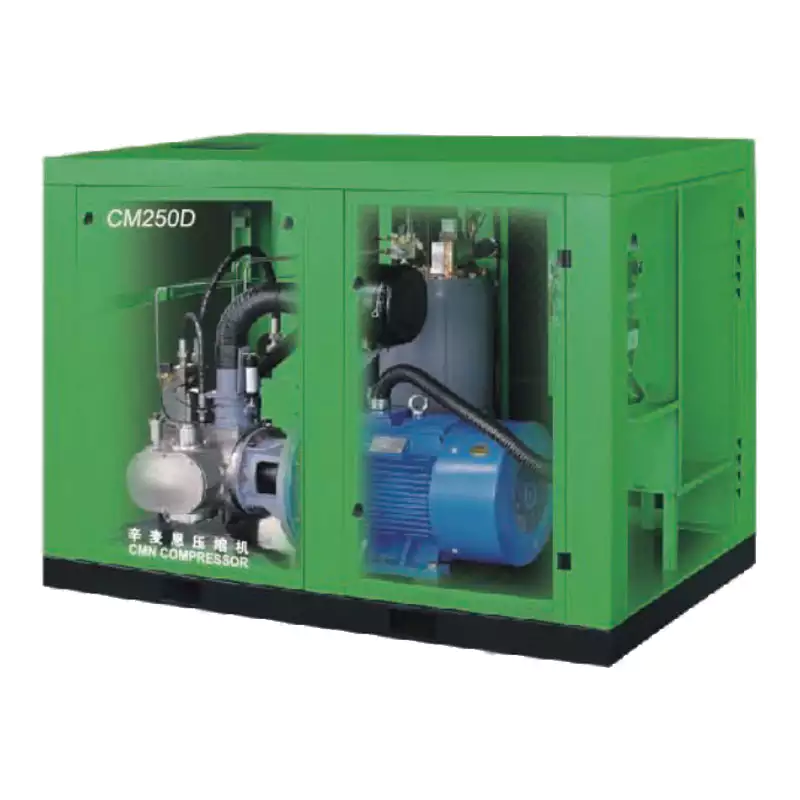
The CM45D’s water-lubricated compression technology delivers a significant ventilation advantage over dry oil-free designs: because water absorbs compression heat at the point of generation, discharge temperatures are 40–60°C lower than equivalent dry oil-free machines. This directly reduces the room heat rejection rate — a 45 kW water-injected unit typically rejects 10–15% less heat to the room than a dry oil-free equivalent at the same power rating. For facilities where the ventilation calculation is tight, the CM45D’s lower heat rejection can be the difference between a standard ventilation system and a costly mechanical cooling addition.
Frequently Asked Questions
Australia Oil Free Air Compressor Co., Ltd.
Charlton Industrial Area, Australia | [email protected]