Why Piping Design Matters for Oil-Free Compressed Air
Oil-free compressed air systems have higher stakes for pipework quality than oil-injected systems. In an oil-lubricated system, trace oil carryover provides a thin film on pipe walls that reduces corrosion and partially seals small pinholes. In an oil-free compressed air system, there is no such protection — corrosion products from carbon steel pipe can contaminate the air stream, pipe joints rely on their own integrity, and any moisture in the system has no oil film to suppress microbiological growth.
The consequences of poor pipework in an oil-free system are particularly visible in quality-critical applications. A pharmaceutical facility with certified ISO 8573-1 Class 0 air from the compressor can fail its air quality audit if corrosion particles from old steel pipework exceed the Class 1 particle limit downstream. A food processing line with a correctly specified desiccant dryer can still have moisture problems if the pipework has dead legs where condensate pools and backs up during demand spikes. These problems are entirely a function of pipework design and material — not the compressor.
The standards governing compressed air piping in Australia include AS 4041 (Pressure Piping) and the applicable sections of AS 1345 (Identification of Piping). All compressed air pipework above 50 kPa gauge pressure must be designed and installed in compliance with these standards — and pressure tested before commissioning.
Pipe Material Selection for Oil-Free Systems
The choice of pipe material affects system longevity, air quality, installation cost, and future maintainability. For oil free compressor applications, the absence of oil carryover means corrosion is the primary material selection criterion — and different materials behave very differently over a 15–20 year pipe system service life.
Pipe Sizing: Minimising Pressure Drop Across the Distribution System
Undersized pipework is the most common cause of tool underperformance in facilities where the compressor itself is correctly specified. Pressure drop in compressed air distribution is proportional to the square of velocity — a pipe carrying twice the flow at the same diameter experiences four times the pressure drop. Getting the pipe diameter right is therefore a cubic relationship with flow rate: halving pressure drop at the same flow requires roughly 1.2× the pipe diameter, not a small change.
The governing design criterion for compressed air piping sizing is maximum allowable pressure drop per unit length. For most industrial systems, this is specified as 0.1 bar (1.5 PSI) per 100 metres of equivalent pipe length at design flow — or total system pressure drop (compressor to furthest point of use) not exceeding 0.5 bar (7.5 PSI). For sensitive instruments or precision processes, design to tighter limits: 0.03–0.05 bar total system drop.
Pipe Sizing Reference Table (Aluminium or Stainless)
| Nominal Pipe Size | Internal Diameter (mm) | Max Flow at 100 PSI (CFM) | Pressure Drop at Max Flow (per 100m) | Recommended Application |
|---|---|---|---|---|
| ½” (DN15) | 15 mm | 12–18 CFM | 1.5–3 PSI | Individual tool drops only — not headers or branches serving multiple tools |
| ¾” (DN20) | 20 mm | 30–45 CFM | 1.5–2.5 PSI | Small workshop sub-header serving up to 4 tools; runs up to 30m |
| 1″ (DN25) | 25 mm | 70–90 CFM | 1.5–2.5 PSI | Medium facility main header up to 50m; ring main for small facilities |
| 1¼” (DN32) | 32 mm | 120–150 CFM | 1.0–2.0 PSI | Large workshop or production line main header; typical medium factory ring main |
| 1½” (DN40) | 40 mm | 200–250 CFM | 1.0–2.0 PSI | Heavy manufacturing main; ring main for medium-large facility up to 200m perimeter |
| 2″ (DN50) | 50 mm | 350–420 CFM | <1.0 PSI | Industrial plant main; large facility ring main |
| 2½”+ (DN65+) | 63 mm+ | 550+ CFM | <0.8 PSI | Major plant main header; laser cutting or PET blowing facility primary distribution |
Note: Flow figures are at 100 PSI system pressure and maximum allowable velocity of 6–9 m/s (design target for low pressure drop). Higher velocities are possible but increase pressure drop and noise significantly. Size pipes for future expansion — upsizing from ¾” to 1″ at installation adds negligible cost versus retrofitting later.
Always include equivalent pipe length for fittings in your sizing calculation. An elbow adds approximately 30 pipe diameters of equivalent length; a tee adds 40–60; a ball valve (open) adds 8–10. A run with 5 elbows in a 25 mm pipe adds approximately 5 × (30 × 0.025) = 3.75 m of equivalent length — significant for a short branch that might otherwise appear adequately sized.
Ring Main vs Radial Distribution: Which Layout for Your Facility
The two fundamental compressed air distribution layouts are radial (also called dead-end or tree) and ring main (loop). Each has distinct pressure distribution characteristics, cost profiles, and maintenance advantages that determine the right choice for different facility types and sizes.
A continuous loop pipe runs the perimeter of the facility (or production area), with branch takeoffs to each use point. The compressor feeds into the loop at one point; air can flow in either direction around the ring to reach any branch.
✅ Localised demand peaks cause less pressure drop at distant points
✅ Sections can be isolated for maintenance without shutting down the full system
✅ Better suited for future expansion — branch connections anywhere on the ring
❌ Higher initial pipe material cost (more linear metres of pipe)
❌ Condensate management more complex — requires drains at low points around the full loop
A main header pipe runs from the compressor room, with branches taken off at each use point or zone. Air flows in one direction only — from compressor toward the end of each branch.
✅ Simpler to design and install
✅ Condensate management straightforward — grade toward a drain at the end of each branch
✅ Suitable for small, compact facilities with simple layouts
❌ Pressure drops toward end of long branches — furthest tools receive lowest pressure
❌ Major demand at one branch affects pressure throughout the system
❌ Full shutdown needed for maintenance on the main header
For medium-sized facilities (1,000–5,000 m²) with multiple production zones, a hybrid approach is common: a ring main in the high-demand production area with radial branches extending to lower-demand zones (offices, stores, maintenance areas). This captures the pressure stability benefits of ring main design where it matters most while avoiding the added pipe cost in lower-density areas.
Condensate Management in Compressed Air Pipework
Even with a correctly specified and well-maintained dryer upstream, compressed air distribution pipework must be designed to manage condensate — the liquid water that forms as air cools from its post-dryer temperature to ambient temperature in the pipework. In a facility with a refrigerated dryer (+3°C dew point), any section of pipework cooler than 3°C will produce condensate. In summer, pipework through an air-conditioned building that is cooler than outdoor temperature may also produce condensate on the outer surface — indicating high moisture content in the air.
Condensate in distribution pipework accumulates at low points, dead legs, and poorly sloped horizontal runs. When air velocity increases during a demand spike, accumulated condensate is picked up and carried downstream — arriving at tools and instruments as slugs of liquid water. This water hammering is particularly destructive in high-pressure systems and in pneumatic instruments with small orifice ports.
Condensate Design Rules
All horizontal pipe runs must slope minimum 1:100 (10 mm per metre) in the direction of airflow. This ensures condensate flows toward a drain point at the end of each run rather than accumulating mid-span. Mark drainage direction on all horizontal pipes during installation.
Automatic drain valves at minimum every 30 metres on horizontal runs, at all low points in the system, at all changes of direction from horizontal to vertical (downward), and at the end of each branch line. For refrigerated dryer systems (+3°C dew point), increase drain frequency to every 20 metres in humid climates.
Electronic zero-loss drains preferred over timer-based types for oil-free systems — they discharge only condensate, not valuable compressed air. Timer drains waste 2–5% of system flow during discharge cycles. In oil-free systems, condensate is clean water and can be discharged to sewer under standard trade waste permits after a conductivity check.
All branch takeoffs from the main header must be taken from the top of the pipe — never from the side or bottom. A top takeoff ensures condensate running along the bottom of the main header does not flow directly into the branch. This is one of the most consistently violated pipework rules and one of the most impactful for tool moisture problems.
A dead leg is any closed-end pipe section — a capped connection installed for future use, an old branch to a decommissioned machine, or a tee fitting with one unused port. Condensate accumulates in dead legs, becomes stagnant, and can develop microbiological growth. Remove unused branches entirely or install automatic drains on capped connections.
Even well-designed systems benefit from point-of-use coalescing filters directly upstream of sensitive instruments, spray guns, or precision actuators. These catch any residual condensate or particulate that survives the upstream filter train — particularly important after distribution system maintenance or in systems with intermittent demand that re-suspends settled condensate.
Compressed Air Leaks: Detection, Cost, and Prevention in Oil-Free Systems
Compressed air leaks are universal in any distribution system — the question is not whether they exist but whether they are actively managed. For oil-free systems, leaks carry a dual cost: the energy waste of producing air that escapes before reaching a useful purpose, and the ingress risk at negative-pressure joints where atmospheric contamination can enter the system.
Modular aluminium push-fit systems typically achieve lower leak rates than threaded steel systems because O-ring joint seals maintain their properties longer than thread compound — and because the push-fit design does not rely on thread engagement force for sealing. However, joint seals can still fail over time, particularly if the pipe is moved or stressed. A structured leak detection programme is essential for any compressed air system regardless of material.
| Leak Detection Method | Cost | Effectiveness | Best Application |
|---|---|---|---|
| Ultrasonic leak detector | AUD $500–3,000 (instrument) | Excellent | Annual audit of full system; detects leaks at rated pressure without system shutdown |
| Soapy water / leak spray | Negligible | Moderate | Accessible joints and connections; misses micro-leaks and inaccessible locations |
| Pressure decay test | No equipment cost | Excellent (quantitative) | Measures total system leakage rate; must be done outside production hours |
| Compressor unload time monitoring | Controller data only | Moderate (trending) | Track average load time over weeks — rising load time at constant production = growing leakage |
The economic case for leak management in oil-free systems is straightforward. A 3 mm diameter leak in a 100 PSI system wastes approximately 25 CFM — equivalent to a medium pneumatic grinder running continuously for no useful purpose. At AUD $0.16/kWh electricity and a compressor efficiency of 5 CFM/kW, this single leak costs approximately AUD $5,000–7,000 per year in wasted energy. Most leak repairs (resealing a joint, replacing an O-ring, tightening a fitting) cost AUD $50–300 in labour and materials. Payback is measured in weeks.
Best practice: annual ultrasonic leak survey, tag all detected leaks, repair during the next scheduled maintenance window. Maintain a leak register. For systems above 100 CFM, a 2% annual leak budget (all detected leaks totalling no more than 2% of system flow) is a reasonable target for a well-maintained modern system.
High-Pressure Piping for Laser Cutting and PET Blowing Systems
For oil-free compressed air systems operating above 175 PSI — common for laser cutting assist gas (175–450 PSI) and PET bottle blowing (600–900 PSI) — pipework design requirements become significantly more stringent. Standard aluminium modular systems are rated to 200 PSI maximum; for higher pressures, schedule 80 stainless steel or schedule 40 carbon steel with internal epoxy lining is required, with all joints welded and pressure-tested to 1.5× maximum working pressure before commissioning.
For high-pressure oil-free systems, the oil free compressor outlet pipework from the compressor to the receiver is the highest-risk section of the installation — high pressure, high temperature (compressor discharge air typically 80–120°C for dry oil-free or 40–60°C for water-injected), and high velocity. This section must use rated high-pressure flexible connectors at the machine outlet and schedule 80 stainless steel or equivalent rigid pipe beyond the flex connection, with all joints either orbital welded or rated high-pressure compression fittings.
Compressed air pipework above 210 kPa gauge (30.5 PSI) and certain bore/pressure combinations must be designed, installed, and pressure-tested in compliance with AS 4041 (Pressure Piping). For pipework above 1,050 kPa (152 PSI), a registered pressure vessel/piping engineer should review the design and certify the installation. Inspections by a competent person are required at defined intervals under relevant state WHS Regulations. Do not commission high-pressure oil-free systems without confirming AS 4041 compliance with a licensed pressure piping installer.
Piping Design Guidance from Australia Oil Free Air Compressor
At Australia Oil Free Air Compressor Co., Ltd., we have found that the difference between a compressed air system that performs at its rated specification for 15 years and one that underperforms from the start is overwhelmingly a piping and installation question — not a compressor question. Our engineering team provides pipework design review as part of every system proposal, covering material selection, header sizing, branch takeoff positions, drain point spacing, and high-pressure section specifications.
For large or complex installations, we offer a detailed piping schematic review service where our team checks the proposed layout against the design guidelines in this article and identifies pressure drop hot spots, condensate accumulation risks, and compliance gaps before any pipe is cut. Catching these issues on paper costs a fraction of correcting them post-installation.
Contact our team at [email protected] to request a piping design review for your facility.
Screw Air Compressor for Laser Cutting — 1.6 MPa Oil-Free
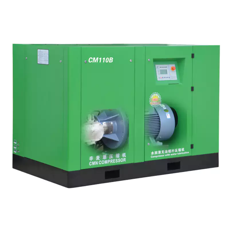
For laser cutting applications where high-pressure oil-free pipework design is most critical, this 1.6 MPa (232 PSI) rated unit illustrates exactly why the complete system approach matters. The compressor outlet pressure, outlet connection size, discharge temperature, and cooling air discharge direction all directly influence the high-pressure pipework design discussed in this article. Our technical data package for this unit includes recommended outlet pipework specifications, flexible connector ratings, and high-pressure distribution guidelines — the documentation your installer needs to build a compliant, high-pressure oil-free system around this machine.
Frequently Asked Questions
Australia Oil Free Air Compressor Co., Ltd.
Charlton Industrial Area, Australia | [email protected]