The Four Functions of an Air Receiver Tank
Before sizing, it is worth understanding exactly what the receiver does — because its four distinct functions have different sizing implications, and facilities with different demand profiles need to prioritise them differently.
Stores compressed air during low-demand periods and releases it during demand spikes. When several tools activate simultaneously and momentary demand exceeds compressor output, the receiver supplies the deficit — preventing pressure sag at the tools. Sizing for this function depends on the magnitude and duration of peak demand events.
Extends the interval between compressor on/off cycles for piston and load/unload controlled screw compressors. Each motor start on a fixed-speed unit generates a 6–8× inrush current and mechanical start-up stress. The larger the receiver, the longer the off-time between cycles — reducing wear and extending motor life for machines that cycle rather than run continuously.
Hot compressed air from the compressor cools in the receiver, causing moisture to condense and settle at the tank bottom — reducing the moisture load entering the downstream dryer. A well-designed wet receiver with an automatic drain removes 40–60% of condensate before the dryer stage, meaningfully extending dryer service intervals.
Provides a brief continuity of supply during a compressor trip, planned maintenance switchover, or filter change — giving production time to complete an in-progress cycle. Most facilities target 30–60 seconds of emergency supply at normal demand. For processes where even a brief pressure loss causes product loss or safety issues, this function drives receiver sizing.
Understanding which function is primary for your application determines the sizing approach. Short-cycle protection dominates for piston compressors. Peak demand buffering is most important for facilities with irregular burst demand (blast cleaning, press cycles, PET blowing). Emergency reserve is the primary consideration for uninterruptable pharmaceutical or food processes. Most practical sizing calculations address the dominant function first and check that the resulting size also adequately serves the others.
The Engineering Sizing Formula: Peak Demand Buffering
The standard engineering formula for receiver sizing is derived from the ideal gas law applied to the pressure drop scenario: the compressor cannot supply peak demand, so the receiver must supply the deficit for a defined acceptable time period.
T = acceptable pressure decay time (minutes)
D = peak demand CFM · C = compressor FAD CFM
Patm = 14.7 psia · P1 = initial pressure (psia) · P2 = minimum acceptable pressure (psia)
Worked Example: Automotive Manufacturing Line
An automotive assembly line has a peak simultaneous demand of 150 CFM during a 2-minute assembly cycle, recurring every 15 minutes. The oil-free rotary screw compressor is rated at 120 CFM FAD. System pressure must not fall below 95 PSI (109.7 psia) from a starting point of 115 PSI (129.7 psia). Target: hold pressure for 3 minutes during peak demand.
V = [3 × 30 × 14.7] ÷ 20
V = 1,323 ÷ 20 = 66.2 cubic feet ≈ 495 gallons
Adding 20% safety margin: 594 gallons → specify 600-gallon receiver
This 600-gallon receiver allows the 120 CFM compressor to serve a 150 CFM peak demand for 3 minutes before pressure falls below the 95 PSI minimum. During the subsequent 12 minutes of below-peak demand, the compressor recharges the receiver ready for the next cycle.
Sizing for Short-Cycle Protection: Piston and Scroll Compressors
For piston and scroll oil-free compressors where duty cycle and short-cycling are the primary life-limiting factors, the receiver must be sized to keep the number of motor starts per hour below the manufacturer’s maximum — typically 6–10 starts per hour for piston units. The formula relates receiver volume to start frequency:
C = compressor output CFM · ALF = average load factor (0 to 1.0)
N = maximum starts per hour · P1/P2 = cut-out/cut-in pressures (psia)
Example: 30 CFM piston compressor, ALF 0.50 (50% average demand), max 8 starts/hour, cut-out 115 PSI, cut-in 100 PSI:
V = 30 × 14.7 × (1 − 0.5) ÷ [8 × (129.7 − 114.7)] = 220.5 ÷ 120 = 1.84 cubic feet ≈ 14 gallons minimum
This is a minimum — in practice, specifying 3–4× this minimum (40–60 gallons for a 30 CFM piston unit) provides comfortable margin for demand variation, ambient temperature effects on duty cycle, and future load growth. Larger receivers pay for themselves in extended valve and ring life on piston compressors.
| Compressor Type & Rating | Recommended Receiver (Rule of Thumb) | Typical Application |
|---|---|---|
| Piston, 5–15 CFM | 20–60 gallons | Single dental chair, small lab, occasional tools |
| Piston, 20–40 CFM | 60–150 gallons | Small workshop, 3–5 tool bay, dental practice |
| Scroll, 30–60 CFM | 80–200 gallons | Medical clinic, electronics assembly, mid-scale lab |
| Rotary Screw (fixed), 60–150 CFM | 100–300 gallons | General manufacturing, food processing |
| VSD Rotary Screw, any size | 0.5 gal/CFM (smaller than fixed) | VSD modulates continuously — large receiver causes control instability |
| High-pulsating demand (blasting, PET) | 3–5 gal/CFM | Sandblasting, PET pre-blow, intermittent press cycles |
VSD Compressors and Receiver Sizing: The Counterintuitive Rule
The most frequently misunderstood receiver sizing scenario involves variable speed drive compressors. Operators often assume that a VSD compressor, because it can ramp to maximum output instantly, still benefits from a large receiver. In practice, the opposite is true: VSD compressors work best with smaller receivers than equivalent fixed-speed machines.
The reason lies in how VSD pressure control works. The VSD controller monitors system pressure and adjusts motor speed to maintain a setpoint (typically ±2 PSI). This control loop depends on pressure feedback — a pressure change in the receiver is the signal that causes the VSD to speed up or slow down. With a very large receiver, pressure changes slowly after a demand event — giving the VSD controller a slow, sluggish signal. The result is a delayed response: the VSD overshoots (ramping too far before the pressure signal catches up), causing hunting and pressure oscillation. In extreme cases, a very large receiver with a small VSD compressor can cause the drive to cycle between minimum and maximum speed erratically — the opposite of the smooth modulation VSD technology is meant to provide.
- → Size at 0.5 gallons per rated CFM maximum
- → Primary functions: moisture separation + emergency reserve only
- → Peak demand buffering handled by VSD speed modulation
- → Verify receiver size against VSD manufacturer’s recommendation
- → If peak demand is highly pulsating (PET blowing, blast), add a secondary dry receiver after the dryer
- → Installing a VSD compressor on an existing large receiver (sized for a previous fixed-speed unit)
- → Causes VSD hunting and poor pressure control
- → May trigger drive protection trips
- → Wastes receiver tank capital that the VSD makes unnecessary
- → Solution: add an isolation valve to use only a portion of the existing receiver volume
High-Pressure Systems: Receiver Sizing for Two-Stage Compressors
A key property of compressed air receivers that affects high-pressure sizing is the relationship between stored energy and volume at pressure. A receiver at 300 PSI stores more than twice as much air mass per unit volume as the same receiver at 145 PSI. This means that for high-pressure applications using two stage air compressors, the same volume of receiver provides proportionally more storage capacity — and sizing rules that apply at 100 PSI produce oversized tanks at 300 PSI.
For high-pressure systems, adjust the basic sizing formula by the ratio of operating pressures. A receiver that would be sized at 200 gallons for a 100 PSI, 100 CFM system needs only approximately 100 gallons if the same system operates at 200 PSI (the higher pressure stores twice the air mass per gallon, so half the volume achieves the same buffer effect). This pressure-adjusted sizing is particularly relevant for laser cutting and PET blowing system receivers.
Vhigh-pressure for 300 PSI system = V100PSI × (114.7) ÷ (314.7) = V100PSI × 0.36
→ A 300 PSI system needs only 36% of the tank volume required at 100 PSI for equivalent air mass storage
How Compressed Air Leaks Degrade Receiver Performance
Compressed air leaks continuously drain the receiver, adding to the demand that the receiver must supply. A system with 20% leakage and a correctly sized receiver for its production demand effectively behaves as though the receiver is 20% undersized — leakage is consuming capacity that should be available for peak demand buffering and short-cycle protection.
The relationship is straightforward: every CFM of leak is a continuous, uncontrolled demand on the receiver. During periods when production demand is low (between cycles, overnight, weekends), leaks drain the receiver continuously — meaning the compressor must refill it from a partially discharged state at the start of each production period. For piston compressors, this increases cycling frequency and reduces effective off-time per cycle, eroding the life-protection benefit of a properly sized receiver.
| System Leakage | Leak CFM (at 50 CFM system) | Effective peak demand buffer remaining |
|---|---|---|
| 5% (new system) | 2.5 CFM | 95% effective |
| 15% (moderate aging) | 7.5 CFM | 85% effective |
| 25% (old system, unaudited) | 12.5 CFM | 75% effective |
| 35% (severe leakage) | 17.5 CFM | 65% effective — tank essentially undersized |
Fix leaks before resizing or replacing receivers. A comprehensive leak audit and repair programme on an existing system often restores effective receiver performance without any tank capital expenditure — because the “undersized” receiver was actually being drained by leaks rather than by production demand.
Australian Compliance Requirements for Compressed Air Receiver Tanks
Pressure vessels — including air receiver tanks — are regulated under the Work Health and Safety (WHS) Regulations in all Australian states and territories. For compressed air receivers, the relevant legislation varies by state but generally follows the risk-based classification framework in AS 3788 (Pressure Equipment — In-Service Inspection) and AS 1210 (Pressure Vessels Design Standard).
Key compliance requirements that affect receiver tank selection and management:
Pressure vessels above specified design pressure × volume thresholds must be registered with the state regulator (SafeWork NSW, WorkSafe VIC, Workplace Health and Safety QLD, etc.). Most industrial compressed air receivers exceed these thresholds. Confirm registration status before commissioning. Unregistered pressure vessels are a WHS compliance failure and insurance coverage risk.
Registered vessels must be inspected by a competent person at defined intervals — typically annual external inspection and 5-yearly internal inspection per AS 3788. Internal inspection is critical for oil-free system receivers: without oil film protection, internal corrosion from condensate is more aggressive than in oil-lubricated systems, and must be assessed at each inspection interval.
Receiver tanks must be designed and manufactured to AS 1210 (or an accepted equivalent standard). Look for the vessel’s Australian Design Registration (ADR) number on the nameplate. Imported receivers without ADR must be independently certified before use in Australian workplaces. Confirm ADR status with your supplier before purchasing.
Receiver Tank Specification from Australia Oil Free Air Compressor
Australia Oil Free Air Compressor Co., Ltd. includes receiver tank specification as a standard component of every system proposal — sized by calculation for your demand profile, compressor type, and operating pressure. We supply ADR-registered carbon steel receivers for standard applications and AS 1210-compliant stainless steel receivers for food-contact and pharmaceutical installations.
Our proposals document the calculation method used — whether engineering formula or rule-of-thumb — and provide sensitivity analysis showing how receiver size affects duty cycle on piston units and pressure stability during peak demand events. This documentation gives you a defensible basis for the specification if the receiver is later questioned in an audit or maintenance review.
Contact us at [email protected] with your compressor model, system flow rate, and demand pattern for a receiver sizing recommendation.
CM110G — Oil-Free Air Compressor for PET Bottle Blowing Applications
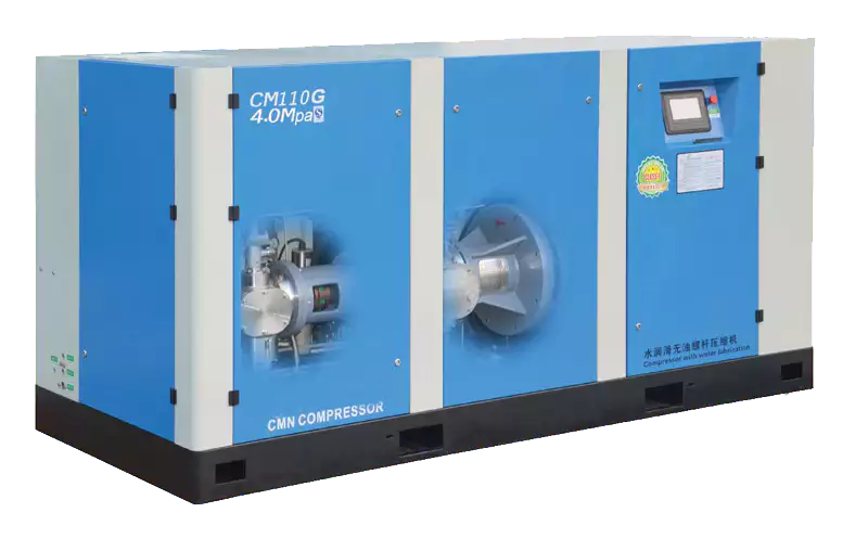
The CM110G for PET bottle blowing represents the most demanding receiver tank sizing scenario in the industrial compressed air sector — high pressure, pulsating peak demand, and zero-tolerance for pressure drop during the blow cycle. The receiver sizing for a PET blowing application is driven entirely by the peak demand buffer function: the receiver must supply the instantaneous high-pressure demand of each blow cycle while the compressor refills between cycles. Our technical documentation for the CM110G includes receiver sizing calculations specifically for common PET blowing machine configurations, reducing the engineering burden on the installation team.
Frequently Asked Questions
Australia Oil Free Air Compressor Co., Ltd.
Charlton Industrial Area, Australia | [email protected]