The Scale of the Problem: Why Contamination Is Different in a Semiconductor Fab
Modern semiconductor manufacturing operates at node sizes measured in nanometres — current leading-edge devices are fabricated at 3–5 nm feature sizes. At this scale, a single hydrocarbon molecule deposited on a wafer surface during a critical process step is not a minor quality deviation — it is a physical contaminant orders of magnitude larger than the feature being manufactured. An oil aerosol particle from a lubricated compressor, even at ISO Class 1 levels (0.01 mg/m³), represents a contamination density that is categorically incompatible with semiconductor wafer processing.
The consequences of hydrocarbon contamination in a semiconductor process are severe and often irreversible. In oxidation processes, surface hydrocarbons inhibit the thermal oxide growth kinetics, producing an oxide with non-uniform thickness and increased defect density. In chemical vapour deposition (CVD), surface hydrocarbons act as nucleation sites for particulate deposition, creating defects that propagate through multiple subsequent layers. In lithography, any organic contamination on the wafer surface scatters the exposure wavelength (particularly EUV at 13.5 nm) and prevents resist adhesion. In each case, the result is yield loss — wafers that cannot be sold — on a process line where a single wafer may contain hundreds of dice worth hundreds of dollars each.
The semiconductor industry’s response to this contamination threat has been to engineer contamination out of every utility system by design, not to manage it by filtration. For compressed air, this means ISO Class 0 oil-free air from an oil-free compressor as the non-negotiable baseline — supplemented by ultra-high-purity filtration that goes significantly beyond what ISO 8573-1 Class 1 filtration provides.
SEMI Standards for Semiconductor Compressed Air and Process Gases
The semiconductor industry’s compressed air and process gas quality requirements are governed primarily by SEMI (Semiconductor Equipment and Materials International) standards — the global body that sets equipment, materials, and process specifications for the semiconductor supply chain.
Where Compressed Air Is Used in Semiconductor Fabrication
Compressed air in a semiconductor fab is not a general utility — it is divided into distinct quality levels depending on the proximity to wafer processing. Understanding the use point hierarchy is the first step in designing an appropriate compressed air system for a fab environment.
Instrument air for process tool pneumatics inside the cleanroom: wafer handlers, robotic arms, valve actuators, chuck clamping. Air that could potentially contact wafers or wafer-handling surfaces. This is the highest quality tier — SEMI F75 specification with total hydrocarbon ≤10 ppb. Only water-lubricated or high-quality dry oil-free compressors are acceptable sources.
Compressed air for systems that support cleanroom processes but are not inside the cleanroom itself: chemical mechanical planarisation (CMP) slurry delivery, photomask storage purging, clean dry room (CDR) equipment. ISO 8573-1 Class 1:1:0 from an oil-free compressor with desiccant drying and high-efficiency filtration. Not required to meet SEMI F75 total hydrocarbon specification.
Compressed air for non-process systems in the fab building: HVAC controls, building management systems, fire suppression system actuators, general maintenance tools. Still requires ISO Class 0 oil from an oil-free compressor — even general utility air in a semiconductor facility must not introduce hydrocarbon contamination risk to the building environment. Desiccant drying to Class 2 water (−40°C) prevents moisture-related issues in instrument and control pneumatics.
Compressed air for office buildings, cafeteria equipment, workshop maintenance, and loading dock pneumatics physically separated from the fab building. Oil-free compressor still strongly recommended to maintain consistent contamination philosophy across the site. Refrigerated drying (Class 3/4 water) is adequate for these non-critical applications.
How Oil Contamination Destroys Semiconductor Devices
Understanding the specific failure mechanisms that oil contamination causes in semiconductor processing helps explain why Class 0 is not merely a best practice but an engineering necessity at sub-10nm process nodes.
At transistor gate dielectric thicknesses of 1–5 atomic layers, a single hydrocarbon molecule at the gate oxide interface introduces fixed charge and interface traps that shift threshold voltage, degrade carrier mobility, and increase leakage current. Device electrical characteristics drift from specification — devices that pass fabrication testing fail in system-level operation under electrical stress.
Hydrocarbon vapour in extreme ultraviolet (EUV) lithography scanners polymerises under EUV photon bombardment to form solid contamination on reflective optical surfaces. A contamination layer just 0.1 nm thick on an EUV mirror degrades its reflectivity by several percent — reducing exposure dose, increasing defocus errors, and causing critical dimension (CD) variation across the wafer. This is why fab cleanrooms are maintained at hydrocarbon levels below 1 ppb.
In atomic layer deposition (ALD) and chemical vapour deposition (CVD), hydrocarbon contamination on the wafer surface before deposition acts as a nucleation inhibitor — preventing the uniform layer growth that these processes depend on. The result is non-uniform film thickness, island-mode growth, and pinhole defects in films that must be continuous for device functionality. Even at sub-ppb contamination levels, ALD processes operating at elevated temperatures can detect and be affected by surface hydrocarbon presence.
Beyond direct wafer contamination, oil-lubricated components in pneumatic systems inside or adjacent to the cleanroom generate lubricant-contaminated particulate from seal wear, valve actuator operation, and solenoid coil heating. These particles can migrate into the cleanroom air stream — bypassing HEPA filtration that is designed for atmospheric particles, not process gas contamination. Oil-free pneumatic actuators and oil-free compressed air eliminate this particle generation source entirely.
Water contamination in pneumatic tool actuators and valve bodies in semiconductor process equipment causes accelerated corrosion of precision stainless steel and aluminium components. Corrosion particles contaminate the wafer-handling mechanism, transferring metal contamination to wafer surfaces. Metal contamination (Fe, Cu, Na, K) at parts-per-trillion concentrations on silicon wafers causes deep-level trap formation that severely degrades minority carrier lifetime — a critical parameter for advanced logic and memory devices.
Semiconductor yield is a compounding function — a 1% defect density per layer across 30 process layers results in approximately 26% total die loss from that single defect source. An oil contamination event that causes a 2% increase in defect density at one critical layer degrades total wafer yield by 3–5 percentage points across the entire lot affected. At wafer values of AUD $2,000–10,000 per 300mm wafer for advanced nodes, the financial impact of a single contamination event is immediately measurable in tens to hundreds of thousands of dollars.
Complete Semiconductor Fab Compressed Air System Specification
A semiconductor fab compressed air system for cleanroom tool air must meet requirements that go significantly beyond standard industrial oil-free systems. The following specification represents the industry standard for critical (cleanroom) compressed air in a semiconductor facility:
| Parameter | Semiconductor Fab Requirement | Standard Industrial Oil-Free | Achieving Technology |
|---|---|---|---|
| Total hydrocarbons | ≤ 10 ppb (SEMI F75) | ≤ 0.01 mg/m³ (ISO Class 1 oil) | Water-lube oil-free compressor + UHP carbon + UHP point-of-use polisher |
| Particle count (≥0.1 µm) | ≤ 100 particles/m³ | ≤ 20,000 particles/m³ (ISO Class 1) | UHP point-of-use filter (0.003 µm membrane) |
| Pressure dew point | ≤ −70°C | ≤ −40°C (ISO Class 2) | Heated desiccant dryer (blower purge or external heat) |
| Metal ion content | ≤ 1 ng/m³ per element | Not specified in ISO 8573 | SS316L distribution pipework; PTFE-lined filter housings; UHP point-of-use filter |
| Microbiological content | Non-detectable (ISO 8573-7) | Not typically specified | Desiccant drying (−70°C eliminates moisture for microbiological growth) + UHP filter |
| System availability | ≥ 99.9% (n+1 redundancy) | Not specified | N+1 compressor configuration; redundant dryers; uninterruptible pneumatic isolation valves |
| Outlet pressure stability | ±0.1 bar at tool connection | ±0.3–0.5 bar typical | VSD compressor with cascaded pressure control; adequate receiver volume; low-loss distribution ring |
The particle requirement (≤100 particles/m³ at ≥0.1 µm) is particularly notable — it is 200× stricter than ISO 8573-1 Class 1 (≤20,000 particles/m³ at 0.1–0.5 µm). This cannot be achieved by standard compressed air filtration. UHP (ultra-high-purity) point-of-use filters with 0.003 µm membrane grade and PTFE-lined housings are required to achieve and maintain this level at tool connections inside the cleanroom.
Semiconductor Fab Compressed Air Architecture: N+1 Design and Zoning
A semiconductor fab compressed air system is engineered around two non-negotiable principles: quality segregation (different quality levels for different zones) and redundancy (no single point of failure for critical supply). The architectural approach that satisfies both principles is a zoned ring distribution system fed from a redundant compressor station.
The compressor station supplies the entire fab. For a typical 300mm wafer fab requiring 1,000–3,000 CFM of compressed air, this means 3–6 compressors in parallel — all oil-free — where N is the number required to supply full demand and +1 is a hot standby unit that starts automatically on failure of any running unit. All compressors feed a common wet receiver before the dryer train.
VSD compressors are preferred for the lead machine (variable demand matching) with fixed-speed standby units. Automatic load-sharing controls distribute operating hours evenly across all units to equalise maintenance intervals.
The treatment train — dryers, filters, and carbon adsorbers — is also designed with N+1 redundancy. Two full-capacity dryers are installed; only one operates at a time, with automatic switchover on dryer malfunction or maintenance requirement. Each dryer has its own filter train upstream and downstream to prevent cross-contamination during switchover.
For heated desiccant dryers targeting −70°C pdp (ISO Water Class 1), regeneration cycles are managed to ensure continuous output of dry air without cyclic dew point variation during vessel switching.
Ring main distribution inside cleanroom; SS316L orbital-welded pipework; PTFE-lined fittings; UHP point-of-use filter (0.003 µm) at each tool connection; continuous dew point monitoring.
Supply from main treatment train; SS316L or aluminium pipework; standard coalescing filter at each major sub-header; periodic dew point monitoring; no UHP point-of-use filter required.
May be supplied from separate compressor station if physical isolation is required; standard industrial oil-free system with refrigerated or desiccant drying; aluminium or standard pipework.
Compressed Air Monitoring in Semiconductor Fabs
Continuous or near-continuous monitoring of compressed air quality is standard practice in semiconductor fabs — not periodic annual testing as in other industries. The speed of contamination impact (a single processing lot affected) and the value at risk (hundreds of wafers per tool lot) justify investment in real-time monitoring instrumentation that provides immediate alerts on quality exceedance.
| Monitoring Parameter | Instrument Type | Location | Frequency | Action on Exceedance |
|---|---|---|---|---|
| Dew point | Capacitive/mirror dew point transmitter | Dryer outlet + cleanroom header | Continuous | Automatic switchover to standby dryer; tool hold if cleanroom dew point exceeds −60°C |
| Particle count | Laser particle counter (0.1 µm sensitivity) | UHP filter outlet (cleanroom) | Continuous or daily | Tool hold; filter integrity investigation; lot traceability review if wafers processed during event |
| Total hydrocarbons | Flame ionisation detector (FID) or cavity ring-down spectroscopy | Carbon adsorber outlet | Continuous (if FID) or quarterly (lab) | Carbon element replacement; investigate source of hydrocarbon increase |
| System pressure | Calibrated pressure transmitter (±0.01 bar accuracy) | Multiple points in distribution ring | Continuous | Start standby compressor if pressure drops below setpoint; alert maintenance on abnormal pressure drop pattern |
All monitoring data is typically integrated into the fab’s Facility Monitoring System (FMS) or Equipment Engineering System (EES) — the same systems that monitor process tool status, environmental conditions, and chemical delivery. Compressed air quality alerts feed directly into the lot hold system, enabling automatic wafer lot quarantine when a quality exceedance is detected during processing.
Semiconductor-Grade Compressed Air from Australia Oil Free Air Compressor
Australia Oil Free Air Compressor Co., Ltd. supplies oil-free compressor systems for semiconductor-related facilities including assembly and test operations, compound semiconductor manufacturing, MEMS fabrication, and academic research fabs. Our water-lubricated oil-free compressor technology provides the structural Class 0 oil guarantee that semiconductor facility engineers require — zero oil in the compression element, zero oil carryover risk from the compression process.
We work with semiconductor facility engineering teams and EPC contractors to specify the compressor station as part of the complete compressed air utility design — from N+1 compressor configuration through dryer selection, filter train specification, and distribution architecture. Our team understands that semiconductor compressed air is not a commodity utility but a controlled manufacturing input that requires the same engineering rigour as the process equipment it serves.
Contact us at [email protected] with your facility type, required air quality specification (SEMI F75 or ISO 8573-1 class), and system flow requirements for a technical proposal.
CM132DV — Water-Lubricated Oil-Free VSD Screw Compressor for Semiconductor Facility Applications
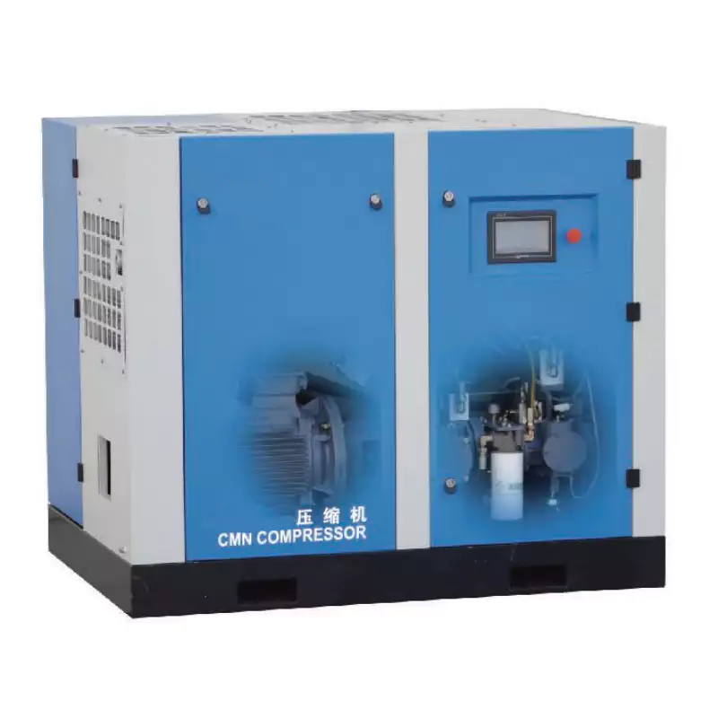
The CM132DV water-lubricated oil-free screw compressor is the appropriate foundation for semiconductor assembly and test facilities, compound semiconductor fabs, and research fabs requiring reliable Class 0 oil supply at industrial scale. Its water-lubricated compression provides zero oil carryover from the compression element — the structural starting point for SEMI F75-compliant compressed air. The VSD drive provides the pressure stability and demand-following performance that semiconductor tool pneumatics require, while the continuous-duty rating enables heated desiccant dryer integration for −70°C dew point (ISO Water Class 1) at the lowest energy cost. Available with full material declarations for semiconductor facility qualification documentation.
Frequently Asked Questions
Australia Oil Free Air Compressor Co., Ltd.
Charlton Industrial Area, Australia | [email protected]