Troubleshooting Guide
A compressor that runs but won’t build pressure — or builds pressure too slowly, or loses pressure the moment it stops — has one of a surprisingly short list of root causes. This guide walks through every cause systematically, from the most common (a downstream leak) to the most serious (a failed compression element), giving you the tools to diagnose your oil-free air compressor correctly the first time and avoid unnecessary parts replacements.
✦ Systematic Root-Cause Diagnosis
✦ 9 Causes Ranked Most → Least Common
✦ Tools Required + Repair Actions
Before You Start: Define the Fault Precisely
The single most common diagnostic error is treating “not building pressure” as a single fault. In practice, there are four distinct pressure-related fault presentations, each with a different set of root causes. Identifying which presentation you have eliminates 50–70% of the possible causes before you open a panel.
Fault A — Runs but pressure never rises
The motor is running, the compressor sounds like it is working, but the pressure gauge stays at zero or near-zero regardless of how long it runs. Air is flowing somewhere — either out of a large leak or straight through a failed compression element without being compressed.
Most likely: massive downstream leak · failed intake valve · belt slip/coupling failure
Fault B — Pressure builds slowly, never reaches setpoint
The compressor runs continuously, pressure climbs over many minutes but plateaus well below the normal cutout pressure — or reaches setpoint but takes two or three times longer than usual. Output capacity is below rated CFM.
Most likely: blocked intake filter · partially open drain valve · moderate air leak · worn compression element
Fault C — Reaches setpoint, then cycles too frequently
The compressor builds to cutout pressure, shuts off, but pressure drops back to cut-in pressure far faster than normal — triggering a restart within seconds to a couple of minutes when no air is being used. Short-cycling that wears motor and compressor components.
Most likely: check valve failure · air leak (moderate size) · pressure switch fault · undersized receiver
Fault D — Reaches setpoint but pressure drops at tool
The compressor gauge shows correct pressure, but tools connected downstream perform poorly — insufficient pressure at the point of use, rapid pressure drop during operation. The compressor itself may be fine; the problem is between compressor and tool.
Most likely: undersized pipework · excessive pressure drop across filter/dryer · regulator set too low · piping restriction
🛠️ Tools You Need Before Starting
Calibrated pressure gauge (not the panel gauge — it may be faulty) · soapy water spray bottle or ultrasonic leak detector · clamp-type ammeter · tachometer (if belt-driven) · service manual for your specific compressor model. Do not rely on the panel pressure gauge for diagnosis until you have verified it is reading correctly against a calibrated reference gauge.
The Systematic Diagnosis: Start Here Every Time
Follow these steps in sequence. Each step either resolves the fault or eliminates a category of causes, narrowing toward the root cause efficiently. Skipping steps — for example, jumping straight to the compression element when the fault might be a leaking drain valve — is the main source of unnecessary downtime and parts cost.
1
Verify the pressure gauge itself (2 minutes)
Connect a calibrated reference gauge to a convenient tee or test point near the receiver. Compare its reading to the panel gauge with the compressor running. A faulty Bourdon tube gauge can read 0 when system pressure is normal — misdiagnosing the entire fault.
Result A: Reference gauge reads normal pressure → panel gauge is faulty. Replace gauge. No further diagnosis needed.
Result B: Reference gauge confirms low/zero pressure → proceed to Step 2.
2
Check all drain valves and manual blow-off valves (3 minutes)
This is the most common cause found in the field — and the most embarrassing to miss. Walk the complete system: receiver drain, dryer drain, filter bowl drain valves, and any manual isolation or blow-off valves. Listen and feel for airflow. An automatic drain that has failed open continuously vents the receiver. A manual valve left open after a service drains pressure as fast as the compressor can build it.
Found an open valve: Close it. Monitor pressure. If pressure builds normally within the expected time, the fault is resolved — inspect and repair or replace the drain valve.
All valves confirmed closed: Proceed to Step 3.
3
Isolate the system — leak test with isolation valve (5 minutes)
Close the isolation valve between the receiver and the downstream distribution system. Run the compressor to full pressure. Shut the compressor off. Watch the pressure gauge for 10 minutes. If pressure holds: the leak is downstream of the isolation valve (in distribution pipework or connected equipment). If pressure drops rapidly: the leak is in the compressor, receiver, or treatment components upstream of the isolation valve — or the check valve has failed.
Pressure holds with isolation closed: Downstream leak confirmed. Open the isolation valve slowly and walk the distribution system with soapy water or a leak detector. Repair all found leaks and retest. This is the most common cause of Fault B (slow pressure build) and Fault C (short cycling).
Pressure drops with isolation closed: Upstream fault. Proceed to Step 4 (check valve) and Step 5 (upstream components).
4
Inspect the check valve (non-return valve) (10 minutes)
The check valve sits between the compressor outlet and the receiver. When the compressor stops, it prevents receiver pressure from back-flowing into the compression chamber. A failed check valve (stuck open or seat damaged) causes pressure to bleed back through the compressor when it stops — presenting as Fault C (rapid pressure drop after cutout) or Fault A (compressor cannot build against the back-pressure from the receiver on restart).
With the compressor shut off and isolated, depressurise the line between the compressor outlet and the check valve. Carefully remove the check valve. Inspect the disc/ball and seat for wear, cracking, scale deposits, or debris preventing closure. Test by blowing through the valve in the reverse-flow direction — air should not pass freely.
Check valve failed: Replace with OEM-equivalent or rated aftermarket valve. Retest pressure hold.
Check valve serviceable: Reinstall and proceed to Step 5.
5
Inspect the intake air filter (5 minutes)
A severely blocked intake filter is one of the most common causes of slow pressure build and reduced output on oil-free air compressors — and one of the most overlooked during troubleshooting because the filter element is not visible without opening the filter housing. A clogged element restricts the mass flow of air entering the compression chamber, directly reducing the compressor’s output capacity. In severe cases, the restriction causes the compression element to cavitate or the inlet pressure to drop sufficiently low that rated discharge pressure cannot be achieved.
Remove the intake filter element and inspect it visually. Hold it up to a light source — heavy dust loading will block the light noticeably. Check the service hours since last element replacement against the manufacturer’s interval (typically 2,000–4,000 hours, or shorter in dusty environments). As a quick test, run the compressor briefly with the filter element removed (outdoors or in a clean environment only) — if pressure build rate improves dramatically, the filter is confirmed as the restriction.
Filter blocked: Replace element immediately. Never clean and reuse a paper or synthetic media element — cleaning damages the media fibres and the element will not filter effectively even if it appears clean after washing.
Filter serviceable: Reinstall and proceed to Step 6.
6
Check drive system — belt tension, coupling, and motor speed (15 minutes)
On belt-driven compressors, a slipping or broken belt is a direct cause of Fault A (no pressure build). The motor runs at full speed but the compressor element is not turning, or turning too slowly to build meaningful pressure. On direct-drive compressors connected via flexible coupling, a sheared coupling insert produces the same result — motor spins, compressor doesn’t.
With the compressor shut off and electrically isolated (lockout/tagout), inspect the drive belt for wear, glazing, cracking, or complete breakage. Check belt tension — a belt should deflect 10–15mm per 300mm of span under moderate finger pressure. Overtight belts wear bearings; loose belts slip under load. Check the belt sheave/pulley alignment. On direct-drive units, inspect the coupling insert for rubber deterioration or shear.
Belt slipping/broken or coupling sheared: Replace with correct OEM belt (note: V-belt matched sets must be replaced as a complete set, not individual belts). Retension to manufacturer specification and retest.
Drive system normal: Proceed to Step 7.
7
Inspect the pressure switch and minimum pressure valve (15 minutes)
The pressure switch controls when the compressor motor starts and stops based on receiver pressure. A faulty pressure switch can cut the motor out at a lower pressure than intended (causing apparent “can’t reach setpoint”) or fail to cut in (causing the compressor never to restart after reaching cutout). The minimum pressure valve (fitted on the compressor outlet on screw compressors) maintains a minimum back-pressure in the compression element during unloading — a failed minimum pressure valve can cause pressure to drop rapidly after cutout.
Check the pressure switch cut-in and cut-out settings against the nameplate specification. On adjustable switches, the adjustment screw may have vibrated out of position. Confirm that the switch is actually cutting out at the stated pressure by watching the gauge at cutout. On screw compressors, check that the minimum pressure valve (located on the discharge side of the airend) is closing properly when the unit unloads — a stuck-open minimum pressure valve causes air to escape back through the unloader during unloaded operation.
Pressure switch mis-set or faulty: Readjust to correct differential or replace the switch. Do not attempt to adjust a pressure switch beyond its rated range.
Minimum pressure valve faulty (screw compressors): Service or replace the minimum pressure valve cartridge.
Both serviceable: Proceed to Step 8.
8
Test intake valve and unloader operation (screw/reciprocating specific) (20 minutes)
On oil-free screw compressors: The inlet valve (butterfly or poppet type) modulates air intake under VSD control and closes completely to unload the compressor when demand drops. A stuck-open inlet valve allows the compressor to re-pressurize rapidly but also prevents proper unloading — the compressor runs continuously at full load even with no downstream demand. A stuck-closed or slow-responding inlet valve starves the airend, causing low output identical to a blocked filter but without the filter pressure drop signature.
On oil-free piston compressors: The inlet and outlet reed valves in each cylinder head are the primary compression mechanism. A failed reed valve (cracked, deformed, or stuck open) eliminates compression in that cylinder. On a two-cylinder compressor, a single failed valve reduces output by 50%; both cylinders failed produces Fault A (no pressure build). Reed valve failure produces a characteristic reversal of airflow — the affected intake port may blow air out rather than drawing it in, detectable by hand near the intake.
Inlet valve or reed valve failed: This is a specialist repair requiring the compression element to be disassembled. Obtain OEM valve kit and follow manufacturer service procedure, or contact authorised service agent.
Valves serviceable: Proceed to Step 9 — compression element assessment.
9
Assess the compression element — worn rotors, rings, or Teflon tips (specialist)
If all upstream causes have been eliminated, the fault is internal to the compression element. On oil-free screw compressors, wear of the rotor profiles (usually the PTFE/polymer coating on rotor lobes in dry screw designs, or water seal wear in water-lubricated designs) increases the clearance between rotors and between rotors and the casing — air slips from the high-pressure outlet side back to the low-pressure inlet side internally, reducing volumetric efficiency and discharge pressure. This is a gradual process in normal operation but can be accelerated by dry running, contamination ingestion, or operating above rated pressure.
On oil-free scroll compressors, wear of the PTFE tip seals causes the same internal recirculation. On oil-free piston compressors, worn piston rings allow compressed gas to bypass the piston on each compression stroke — this is detectable by excessive air blowing from the crankcase breather during operation.
Compression element wear confirmed: Element rebuild or replacement is required. For screw compressors, this typically means returning the airend to the manufacturer or authorised rebuild centre. For piston compressors, a ring and valve rebuild kit is available for most models and can be completed by a competent mechanical technician. Contact your compressor supplier for assessment — on water-lubricated models, the water seal condition and rotor clearances are checked during a scheduled service intervention.
All Causes at a Glance: Ranked by Frequency
Based on field service data across oil-free rotary screw and piston compressor models in Australian industrial and commercial applications, these are the causes of low/no pressure build, ordered from most to least common:
| Rank |
Cause |
Fault Presentation |
DIY Repair? |
Typical Repair Cost |
| #1 |
Downstream air leak (piping, fittings, tools) |
B, C |
✅ Yes |
Low — fittings, thread tape, hose replacement |
| #2 |
Drain valve stuck open or manually left open |
A, B |
✅ Yes |
Low — replace auto drain valve |
| #3 |
Blocked intake air filter element |
B |
✅ Yes |
Low — replacement element only |
| #4 |
Failed check valve (non-return valve) |
C |
✅ Yes |
Low-medium — check valve replacement |
| #5 |
Pressure switch mis-set or faulty |
B, C |
✅ Yes |
Low — switch replacement |
| #6 |
Faulty pressure gauge (reading low/zero) |
A, B (apparent) |
✅ Yes |
Low — gauge replacement |
| #7 |
Belt slip / coupling failure (belt-drive units) |
A, B |
✅ Yes |
Low-medium — belt set or coupling insert |
| #8 |
Inlet valve or minimum pressure valve fault (screw) |
A, B |
⚠️ Specialist |
Medium — valve kit + labour |
| #9 |
Worn compression element (rotors, rings, tip seals) |
B |
❌ Specialist only |
High — element rebuild or replacement |
Variable Speed Drive Compressors: Additional Fault Causes
On variable speed drive compressors — which modulate motor speed to match compressed air demand — there are additional fault causes that do not apply to fixed-speed machines. The VSD (inverter drive) controls motor speed in response to discharge pressure feedback. If the VSD is not commanding the correct motor speed, or the pressure feedback signal is incorrect, the compressor will not deliver rated pressure regardless of the mechanical condition of the compression element.
VSD Pressure Setpoint Incorrectly Configured
The target pressure parameter in the VSD or controller has been changed — either during commissioning, after a power event, or by an unintentional parameter modification during servicing. Check the controller display for the active pressure setpoint and compare it to the nameplate or the previous operational setting. On most modern variable speed drive compressor controllers, the setpoint is accessible via the main menu.
VSD Motor Speed Limit Set Too Low
The maximum motor speed parameter (Hz or RPM) in the VSD has been reduced, preventing the compressor from reaching full output capacity. This can occur after a drive replacement if the new drive parameters are set to a generic default rather than the machine-specific values. The compressor runs but output is capped below what is needed to reach target pressure.
Pressure Transducer Fault
The pressure transducer that provides discharge pressure feedback to the VSD controller is reading low. The VSD “sees” a lower-than-actual pressure and commands a motor speed that is appropriate for the lower reading — but the actual system pressure is higher, causing the controller to appear to not reach setpoint when the system is actually close to or at the correct pressure. Compare transducer output to a calibrated reference gauge.
VSD Thermal Derating
In high ambient temperature conditions (common in Australian summer), the VSD drive module reduces maximum output current to protect its internal power electronics — this is called thermal derating. At reduced maximum current, the motor cannot reach its rated torque at all speeds, limiting maximum pressure achievable. Symptoms: compressor reaches normal pressure in cooler morning conditions but cannot reach setpoint by afternoon. Solution: improve VSD cabinet ventilation or install cooling.
Fault D: Pressure OK at Compressor, Low at Tool — Distribution System Problems
If the compressor gauge shows correct pressure but tools or processes receive insufficient pressure, the fault is in the distribution system between the compressor outlet and the tool connection. This is one of the most under-diagnosed fault categories — engineers frequently investigate the compressor when the actual problem is in the pipework.
HIGH LOSS
Undersized distribution pipework
Pipe bore too small for the actual flow demand creates velocity-related pressure drop. At high flow rates, pressure drop across undersized pipework can be 1–3 bar — meaning 7 bar at the compressor becomes 4–5 bar at the tool. Recalculate pipe sizing using actual flow (CFM) at actual pressure against the pipe run length. Typically, velocity should not exceed 6–8 m/s in compressed air mains.
MEDIUM
Blocked or undersized downstream filter/dryer
Filter elements at end of service life, or dryer desiccant beds requiring regeneration, create high pressure differential. Measure pressure upstream and downstream of each treatment component. More than 0.3–0.5 bar drop across a filter or dryer at normal flow indicates a service requirement. Replace filter elements and verify dryer regeneration cycle is operating correctly.
MEDIUM
Regulator set below required pressure
Point-of-use pressure regulators reduce pressure to tool requirements. If a regulator has been adjusted to a lower pressure setting than required — or if the tool requires higher pressure than the regulator allows — tool performance will be poor even with correct upstream system pressure. Check regulator setpoint against tool requirement. Note: never remove a regulator to increase pressure beyond the tool’s rated pressure — this causes tool damage and safety risk.
LOW
Excessive hose length or small-bore hose connections
Long flexible hoses at smaller bore than the distribution pipework create localised pressure drop under high flow. A 10-metre length of 6mm bore hose at 200 L/min flow can produce 1–2 bar pressure drop. Use the shortest practical hose at the largest bore appropriate to the tool connection. Consider a local receiver near high-demand tools to buffer peak flow events.
Preventing the Fault: The Pressure System Maintenance Schedule
The majority of “not building pressure” faults are preventable with a simple maintenance programme. The tasks below address the most common causes before they produce a production stoppage:
Weekly
- → Walk system — listen for air leaks
- → Check drain valves discharging correctly (not stuck open or closed)
- → Verify cut-in/cut-out pressures against setpoint
- → Check VSD display for fault codes
Monthly
- → Inspect intake filter — replace if in doubt
- → Check belt tension and condition (belt drive)
- → Verify check valve function (isolated pressure hold test)
- → Test auto drain valves by manually triggering
- → Measure pressure differential across filter train
Annually (or per service interval)
- → Replace intake filter element
- → Replace check valve disc/seat if worn
- → Calibrate pressure transducer against reference gauge
- → Ultrasonic leak detection survey of full system
- → Verify pressure switch setpoints with calibrated gauge
- → Full scheduled service per manufacturer’s manual
When to Stop and Call a Service Technician
Most pressure faults are diagnosable and repairable without specialist involvement. But there are clear points where calling an authorised service technician is the right decision — attempting further diagnosis without specialist tools or knowledge risks additional damage and safety risk.
⛔
Safety relief valve lifting repeatedly: If the safety relief valve (PRV) opens during normal operation — not just as a one-off event — do not continue running the compressor. The PRV is protecting the system from overpressure caused by a pressure switch or unloader fault. Continuing to run risks PRV fatigue failure and sudden pressure release.
⛔
Abnormal noise from the compression element: Knocking, grinding, squealing, or metallic contact sounds from inside the airend indicate internal mechanical damage. Stop the compressor immediately — continued running with internal damage causes catastrophic element failure.
⛔
Motor tripping on overload: If the motor overload protection is tripping during pressure build, there is an electrical fault, a locked rotor condition, or excessive load on the compression element. Do not reset and restart without identifying the cause.
⛔
VSD drive fault codes you cannot identify: VSD fault codes indicating power module faults, IGBT failure, or encoder errors require a qualified electrician or VSD specialist. Incorrect diagnosis of drive faults can result in drive damage or safety hazards.
For all of the above — and for compression element assessment, inlet valve service on screw compressors, and water seal replacement on water-lubricated models — contact [email protected]. We support all oil-free compressor models we supply with service documentation, spare parts, and field technician assistance throughout Australia.
Recommended Product
CM132DV — Water-Lubricated Oil-Free VSD Screw Compressor: Fewer Pressure Faults by Design
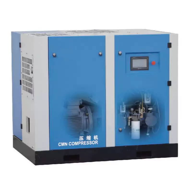
The CM132DV water-lubricated oil-free VSD screw compressor eliminates several of the most common pressure fault causes by design. Water lubrication removes the belt drive and coupling (no belt tension or coupling insert faults), the VSD eliminates the pressure switch (pressure is controlled directly by the drive), and the water-lubricated airend design provides extended element life compared to dry oil-free designs — significantly reducing the risk of progressive wear-related pressure loss. The CM132DV controller provides real-time pressure trend logging, enabling early detection of gradual output decline before it becomes a production fault. All models come with comprehensive service documentation, and spare parts are held in Australia for rapid response to any service requirement.
View CM132DV Specifications
Frequently Asked Questions
How much compressed air leakage is normal in an industrial compressed air system?
+
A well-maintained compressed air system should have leak losses below 5% of total generated compressed air. Systems in average industrial condition typically lose 10–20%. Poorly maintained or aging systems commonly lose 30–40% — meaning the compressor runs almost continuously to keep up with demand that is primarily waste, not production use. A practical way to measure leakage: during a production shutdown (all tools isolated), run the compressor to full pressure, shut it off, and measure how long it takes for pressure to drop from cut-out to cut-in. Divide the receiver volume (in litres) by the drop time (in seconds) to calculate approximate leak rate in L/s. Compare this to the compressor’s rated output to express leakage as a percentage. Any system with more than 10% leakage should have a leak detection survey conducted.
My oil-free compressor reaches pressure but takes much longer than it used to — what has changed?
+
Gradual increase in the time to build pressure indicates a gradual reduction in the compressor’s effective output capacity. The three most common causes — in order — are: a progressively blocked intake filter (fix: replace the element); a slow-developing air leak in the system (fix: leak detection survey and repair); and gradual wear of the compression element over thousands of hours (indicator: compressor is near or past its overhaul interval). Start with the filter (cheapest and most likely), then conduct a leak survey, then assess element condition based on service hours. If the compressor is within its expected service interval and the filter and leaks are addressed, element wear is unlikely to be the cause.
Can I increase the pressure setpoint on my oil-free compressor to get more pressure?
+
Only within the compressor’s rated maximum pressure. The nameplate lists the maximum allowable working pressure (MAWP) — this is the design limit for the compression element, receiver, pipework, and safety devices. Setting the cutout pressure above this limit creates a safety hazard and will cause the safety relief valve to lift continuously. If your application genuinely requires more pressure than the compressor’s rated maximum, the compressor is undersized for the application — you need a higher-rated model, not an adjusted setpoint. For most standard oil-free rotary screw compressors, rated maximum pressure is 7–10 bar; medium-pressure models reach 13–16 bar; high-pressure speciality units exceed this. Do not attempt to bypass or re-set the safety relief valve — this is illegal under Australian pressure vessel regulations.
Why does pressure drop immediately when I open a valve to use air?
+
A large, immediate pressure drop when air demand starts indicates one of two things: the receiver is undersized for the peak demand event, or the compressor CFM output is lower than the peak demand CFM of the connected tools. The receiver tank acts as a buffer — it stores compressed air at system pressure to cover short-duration peaks that exceed the compressor’s continuous output. If the receiver is too small relative to the peak demand event duration, pressure drops rapidly. The solution is either a larger receiver, a higher-output compressor, or splitting peak demand across time to reduce instantaneous flow. Check that the compressor’s rated CFM at system pressure matches or exceeds the total CFM of all simultaneously operating tools. If it does not, the system is fundamentally undersized and no receiver size will permanently resolve the issue.
What is air compressor duty cycle and how does it affect pressure problems?
+
Duty cycle is the percentage of time a compressor can run loaded (compressing) versus resting (unloaded or stopped) in a given time period. A compressor rated at 60% duty cycle is designed to compress for 36 minutes per hour, with 24 minutes of unloaded or stopped time. If the system air demand requires the compressor to run more than its rated duty cycle, the compressor overheats and the thermal protection cuts it out — which looks like a pressure fault (compressor stops before reaching setpoint, then after a cool-down period restarts and the cycle repeats). Oil-free screw compressors are typically rated at 100% duty cycle; oil-free reciprocating piston compressors are usually rated at 50–75% duty cycle. If you observe the compressor cycling off due to thermal protection rather than reaching the pressure cutout setpoint, duty cycle overload is the likely cause — the compressor is undersized for the actual air demand.