
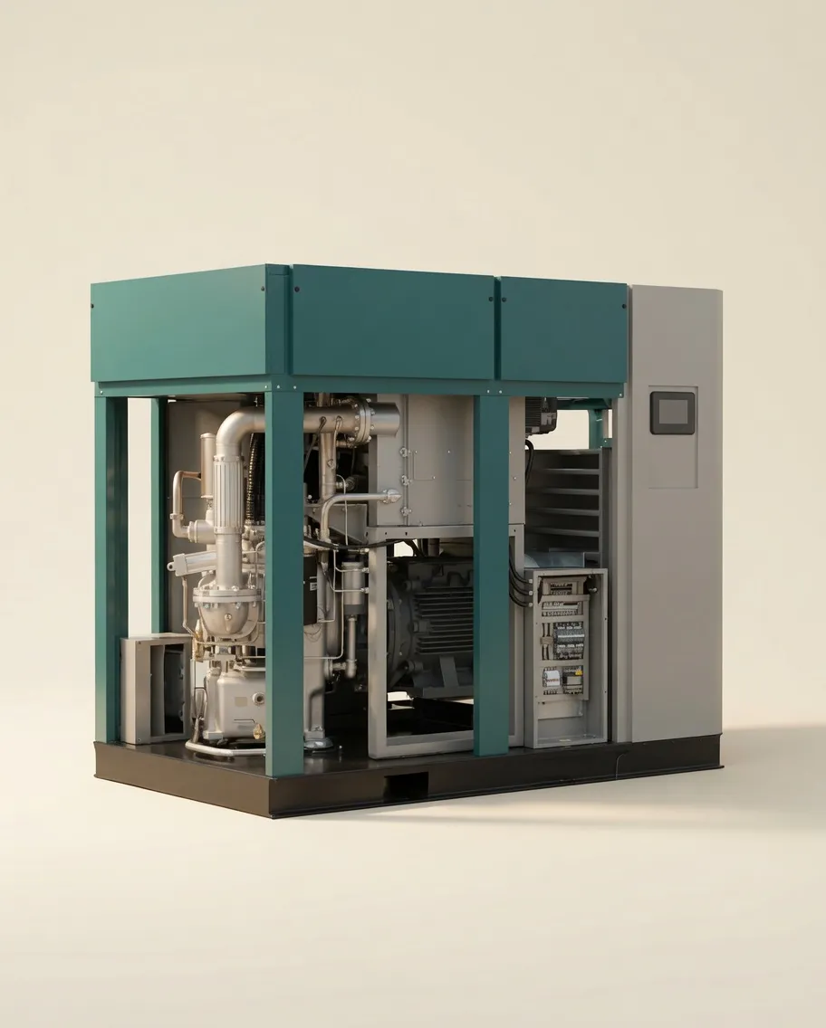
Why CFM Is the Number That Actually Matters
When most people buy an oil-free air compressor, the first number they look at is horsepower. This is understandable — horsepower is visible on the label, easy to compare, and intuitively relates to power. But for pneumatic systems, horsepower is a secondary specification. Air compressor CFM (Cubic Feet per Minute) is the number that determines whether your tools run correctly or starve for air.
Think of it this way: horsepower determines how hard the compressor works. CFM determines how much air it actually delivers. A high-horsepower compressor producing low CFM at your required pressure is useless for high-flow applications — just as a high-flow compressor producing insufficient pressure fails equally. Both figures matter, but CFM is the one that most directly maps to tool performance.
Every pneumatic tool has a minimum CFM requirement at its rated pressure. Fall below it and the tool underperforms: impact wrenches lose torque, spray guns produce inconsistent atomisation, sandblasters slow to ineffective grit flow. The goal of CFM sizing is to ensure your oil free air supply comfortably exceeds the combined demand of every tool you run simultaneously — with margins for leakage, system losses, and future needs.
The 4-Step CFM Sizing Method
Write down every piece of equipment that will draw compressed air — tools, actuators, blow guns, spray equipment. For each, record the manufacturer’s stated CFM at operating pressure. If the manual is lost, use the reference table in the next section. This is your installed demand list.
Not all tools run simultaneously. Sum only the CFM of tools that will operate concurrently during your busiest production window. If you have 8 tools but only 4 ever run at once, use the 4-tool sum as your simultaneous peak demand figure. This is a key step that prevents over-specification.
Add 10% to your simultaneous demand figure for compressed air leaks (new systems) or 20–25% for existing systems without a recent leak audit. If you use a desiccant air dryer, add a further 12–15% for purge air consumption. These additions are not optional — skipping them is the most common cause of an undersized system.
Multiply your running total by 1.15–1.25 to create a headroom buffer for future capacity additions, demand underestimation, and seasonal variation. The resulting figure is your required FAD (Free Air Delivery) — the minimum rated output your compressor must deliver at operating pressure.
Simplified: Required FAD ≈ Peak Simultaneous CFM × 1.50
(The 1.50 multiplier covers leakage + purge + growth in a single step for quick estimates)
Common Tool CFM Reference Table
Use this reference table to look up CFM consumption for tools where manufacturer data is unavailable. All figures are at standard operating pressure (90–100 PSI unless noted) and represent typical mid-range consumption — heavy-duty variants may be 20–30% higher. For precise sizing, always confirm against the tool manufacturer’s specification sheet.
| Tool / Equipment | CFM (Low) | CFM (Typical) | CFM (High) | Duty Cycle Typical |
|---|---|---|---|---|
| Hand Tools | ||||
| Impact wrench (1/2″) | 3 | 4–5 | 6 | 30–50% |
| Impact wrench (3/4″–1″) | 6 | 8–10 | 12 | 30–50% |
| Angle grinder (4″–5″) | 4 | 5–7 | 9 | 60–80% |
| Air drill (3/8″) | 3 | 3–5 | 6 | 40–60% |
| Die grinder | 4 | 5–6 | 8 | 60–80% |
| Air ratchet | 2 | 3–4 | 5 | 25–40% |
| Nail gun / framing nailer | 0.5 | 1–2 | 3 | 10–25% |
| Spray & Finishing | ||||
| HVLP spray gun | 4 | 6–10 | 14 | 70–100% |
| Conventional spray gun | 5 | 8–12 | 16 | 70–100% |
| Orbital sander | 6 | 8–11 | 14 | 80–100% |
| Abrasive & Cleaning | ||||
| Sandblast cabinet (small) | 8 | 12–16 | 20 | 80–100% |
| Sandblast pot (outdoor) | 15 | 25–50 | 80+ | 80–100% |
| Blow gun (standard nozzle) | 1 | 2–4 | 6 | 20–50% |
| Industrial & Process | ||||
| Pneumatic cylinder (50mm bore) | 0.3 | 0.5–1.5 | 3 | Varies |
| Air knife (per foot length) | 5 | 8–15 | 25 | 100% |
| Dental handpiece | 0.5 | 1–1.5 | 2 | 60–80% |
| Plasma cutter | 4 | 5–8 | 10 | 70–90% |
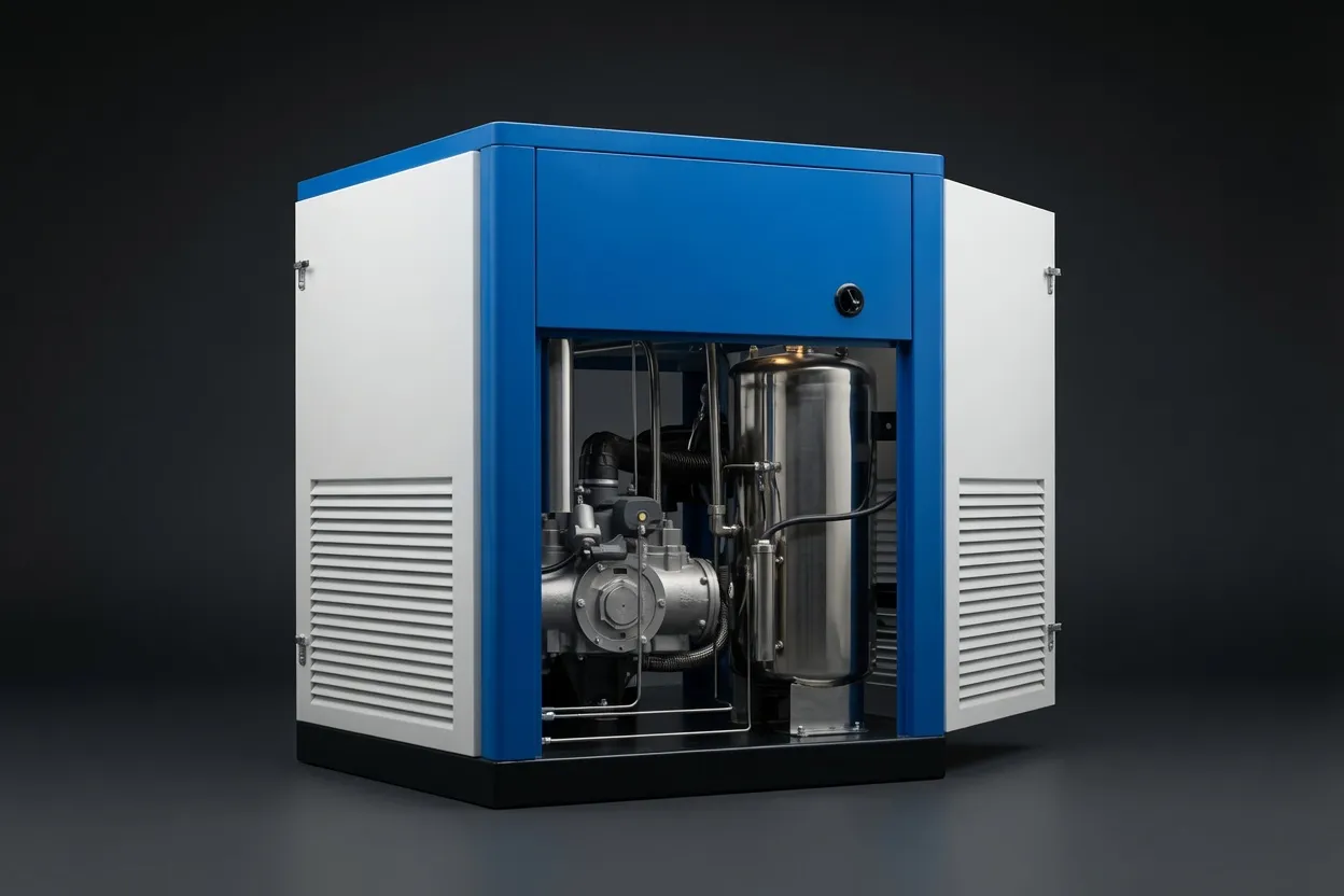
Worked Example: Small Automotive Workshop
An automotive workshop in Brisbane runs the following tools during a typical service shift. The workshop already has piping in place but hasn’t been audited for leaks in four years. Here’s the full CFM calculation from scratch:
| Tool | Qty Running | CFM Each | Tool Duty | Effective CFM |
|---|---|---|---|---|
| Impact wrench (1/2″) | 2 | 5 | 40% | 4.0 |
| Angle grinder | 1 | 6 | 70% | 4.2 |
| Orbital sander | 1 | 9 | 80% | 7.2 |
| Air ratchet | 2 | 3.5 | 30% | 2.1 |
| Blow guns (cleaning) | 2 | 3 | 25% | 1.5 |
| Total simultaneous effective CFM | 19.0 CFM | |||
+ Leakage (25% — older system): + 4.8 → 23.8 CFM
× Growth factor (1.20): × 1.20 → 28.6 CFM
→ Recommended compressor FAD: 30–35 CFM at 100 PSI
A 35 CFM, 100 PSI oil-free compressor would be the appropriate specification here. For this intermittent-use workshop pattern (average duty well below 60%), an oilless air compressor piston design in the 30–40 CFM FAD range is technically appropriate and cost-effective.
5 CFM Sizing Mistakes That Cost Australian Businesses Every Year
These errors appear repeatedly in compressor installations across manufacturing, trade, and process sectors. Each one is avoidable — but only if you know to look for it.
Specifying a compressor based purely on the highest possible demand moment — all tools running at rated CFM simultaneously — almost always results in massive oversizing. Use realistic simultaneity and actual duty cycles, not maximum theoretical demand.
A facility that has not had a compressed air leak audit in the past two years almost certainly has 15–25% leakage. Not building this into the CFM specification means the compressor runs at a higher load factor than anticipated — shortening service intervals and accelerating wear.
Compressor catalogues sometimes list displacement (theoretical) CFM rather than FAD (actual delivery). Displacement CFM is 10–20% higher than FAD for most designs. Always confirm which figure a manufacturer is quoting, and request FAD at your specified operating pressure.
Desiccant dryers consume 10–15% of compressor output for regeneration purge. A 100 CFM compressor feeding a desiccant dryer delivers only 85–90 CFM of usable dry air. This loss is systematic and continuous — failing to account for it creates a permanent shortfall in usable output.
A 10 HP compressor at 100 PSI may deliver 40 CFM. The same 10 HP at 145 PSI delivers only 30 CFM. Two compressors with identical horsepower but different maximum pressure ratings have very different usable outputs at your actual working pressure. Specify the CFM you need at the pressure you operate — not a horsepower rating without pressure context.
When Your CFM Demand Is Variable: The VSD Advantage
If your CFM demand swings significantly during the working day — a common pattern in multi-shift manufacturing, batch processing, or facilities with both continuous and intermittent processes — a variable speed drive compressor delivers a meaningful efficiency advantage over a fixed-speed machine sized for peak demand.
A fixed-speed compressor sized to handle 120 CFM peak demand will run at full power (or cycle on/off) even during periods when demand is only 40–50 CFM. A VSD unit sized for the same peak simply slows its motor speed to match, consuming power proportional to actual demand. Studies consistently show energy savings of 15–35% in variable-demand applications — often representing AUD $3,000–15,000 per year for mid-size industrial users.
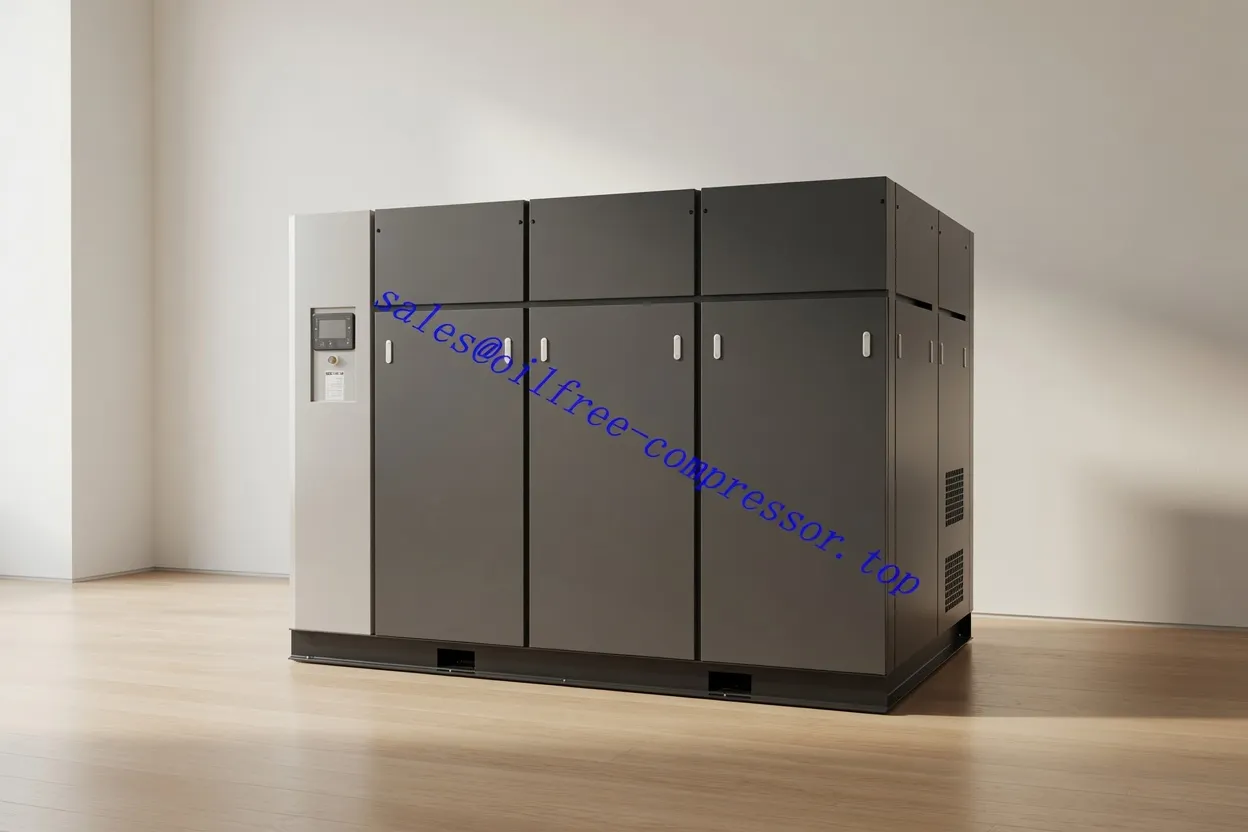
Quick CFM Reference: Application to Compressor Size
This summary table maps common application scenarios to a recommended compressor FAD range, incorporating leakage and growth allowances from the 4-step method. Use this for initial budget planning — confirm with a full calculation before purchasing.
| Application | Typical Simultaneous CFM | Recommended FAD | Suggested Type |
|---|---|---|---|
| Single dental chair | 1–2 | 4–6 CFM | Oil-free piston |
| 4-bay dental practice | 6–8 | 12–16 CFM | Oil-free scroll |
| Auto workshop (3–5 tools) | 15–25 | 30–40 CFM | Oil-free piston or scroll |
| Small spray booth (1–2 guns) | 10–20 | 20–35 CFM | Oil-free scroll |
| Light assembly line (10 tools) | 40–60 | 70–100 CFM | Oil-free rotary screw |
| Medium food processing line | 80–120 | 140–180 CFM | VSD oil-free rotary screw |
| Laser cutting centre (2 machines) | 100–200 | 180–280 CFM | Oil-free rotary screw |
| Large pharmaceutical facility | 200–400 | 300–550 CFM | Multiple oil-free rotary screw |
Get the Right CFM the First Time — Our Engineering Support
Australia Oil Free Air Compressor Co., Ltd. has helped facilities across industrial, food processing, medical, and trade sectors right-size their oil-free compressed air systems from the ground up. Our team at the Charlton Industrial Area facility walks through your tool list, production schedule, and site conditions to arrive at a CFM figure you can rely on — not a rounded-up catalogue number.
We carry a full range from compact oil-free piston units for dental and laboratory use through to high-capacity oil-free rotary screw compressors for continuous industrial operation. Every recommendation comes with a written CFM justification and projected energy cost analysis at your local electricity rate.
Send your tool list and shift schedule to [email protected] and our team will return a recommended CFM specification within one business day.
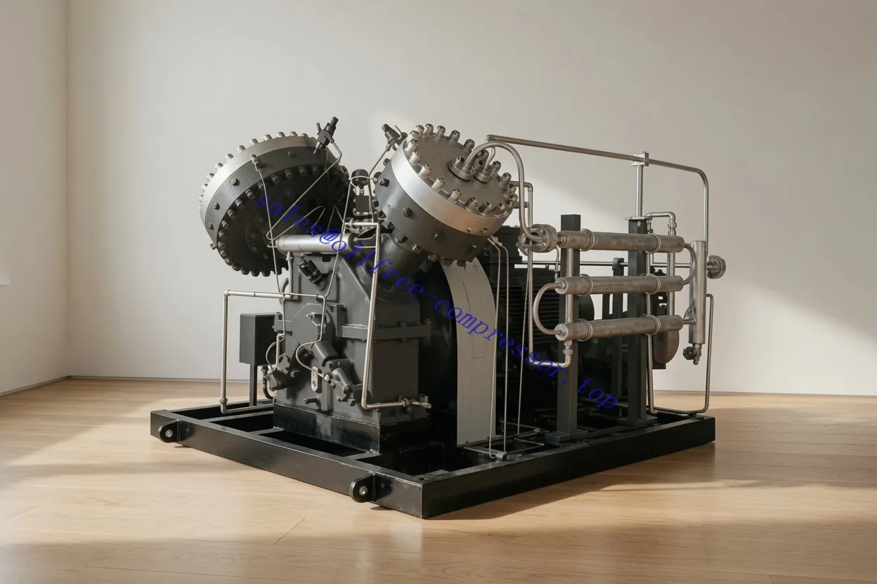
CM22G Series — Oil-Free Screw Air Compressor
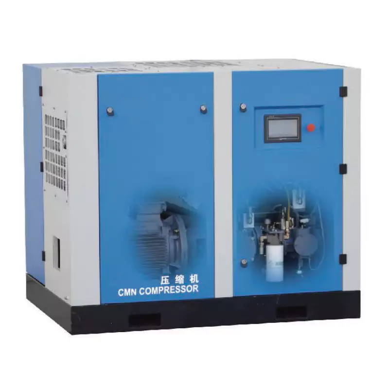
For facilities graduating from an undersized piston unit or making the move to continuous-duty oil-free compressed air for the first time, the CM22G Series delivers a practical entry into industrial-grade CFM performance. Its oil-free rotary screw design provides 100% duty cycle capacity with documented FAD output — removing the sizing uncertainties that come with piston technology at the same price point. Available across a CFM range that covers the 30–120 CFM band most relevant to light and medium manufacturing in the Australian market.
Frequently Asked Questions
Australia Oil Free Air Compressor Co., Ltd.
Charlton Industrial Area, Australia | [email protected]