
Why Sizing an Oil-Free Compressor Is Different
Selecting the right oil-free air compressor is not simply a matter of matching horsepower to a rough application description. Unlike oil-lubricated machines, oil-free units operate with tighter mechanical tolerances — a consequence of their contamination-free design — which means thermal management, cycle frequency, and airflow demand all interact in ways that can shorten equipment life if the sizing is wrong.
Industry data shows that up to 30% of industrial compressor installations are incorrectly sized, with the majority of those errors leaning toward undersizing. The result is short-cycling, premature wear of PTFE coatings or water-injected components, and unplanned downtime — all of which erode the clean-air advantage you paid for in the first place.
The three parameters that govern correct sizing are CFM (Cubic Feet per Minute), PSI (Pounds per Square Inch), and duty cycle. Get all three right and your compressor runs in its designed operating window. Ignore any one of them and you are guessing. The sections below walk through each in sequence, with worked examples at every stage.
Step 1 — Determine Your Total CFM Demand
CFM is the single most important number in compressor sizing. It represents the volume of free air your tools and processes consume per minute. The key word is free air — air at atmospheric conditions — not compressed air. Manufacturers rate their compressors in FAD (Free Air Delivery), so your demand calculation must also be in FAD terms.
List Every Air-Consuming Device
Begin by cataloguing every tool, actuator, valve, and process that draws compressed air. For each one, record the manufacturer’s rated CFM at operating pressure. If a device has a duty cycle of less than 100%, note that too — it directly affects your demand calculation.
Apply the Simultaneity Factor
Not every tool runs at the same moment. The simultaneity factor (also called diversity factor) accounts for this. In a typical workshop environment with 10 tools, all 10 rarely run simultaneously. A simultaneity factor of 0.75 is a conservative industry standard for most manufacturing facilities; dental or medical applications with highly controlled schedules can use 0.65–0.70.
Service Factor = 1.25 (adds 25% headroom for leakage and future growth)
For example: 10 tools totalling 120 CFM installed demand × 0.75 simultaneity × 1.25 service factor = 112.5 CFM FAD. You would select a compressor rated at 115–125 CFM FAD to land inside the operating window without excessive over-spec.
Step 2 — Establish Your Required PSI
Pressure requirements are dictated by the highest-pressure application in your system — but with one important qualifier: the pressure must be measured at the point of use, not at the compressor outlet. Line losses between the compressor and the tool typically consume 5–15 PSI depending on pipe diameter, length, and fitting count. Always size for the end-point requirement.
| Application | Typical PSI at Point of Use | Compressor Outlet PSI | Recommended Max PSI Rating |
|---|---|---|---|
| General workshop tools | 80–90 PSI | 100 PSI | 125 PSI |
| Laser cutting (low-pressure) | 145–175 PSI | 175–200 PSI | 200–250 PSI |
| Laser cutting (high-pressure N₂) | 290–435 PSI | 400–450 PSI | 450 PSI |
| PET bottle blowing | 580–870 PSI | 600–900 PSI | 900+ PSI |
| Dental / medical instruments | 55–80 PSI | 90 PSI | 100 PSI |
| Food & beverage pneumatics | 90–115 PSI | 115–130 PSI | 145 PSI |
If your system spans multiple pressure requirements — for example, a facility running both precision instruments at 80 PSI and a laser cutter at 175 PSI — the correct approach is zone regulation: size the oil-free compressor for the highest pressure, then use point-of-use pressure regulators to reduce supply to lower-demand zones. This is more efficient than running two separate compressors in most facilities under 500 CFM total demand.
Step 3 — Calculate Duty Cycle & Run Time
The duty cycle of an air compressor defines the percentage of time it should be running versus resting within a given time window. For oil-free piston and reciprocating compressors, a maximum duty cycle of 50–60% is typical to prevent overheating of Teflon-coated components. Oil-free rotary screw compressors, by contrast, are designed for 100% continuous duty — a critical distinction when your process demands constant airflow.
Duty Cycle by Compressor Type
Calculating Required Compressor CFM from Duty Cycle
If your process requires 80 CFM but you plan to use a piston compressor rated at 60% duty cycle, the actual delivered CFM over a sustained period is only 0.60 × rated output. This means you need a piston machine rated at approximately 133 CFM to reliably deliver 80 CFM net. The formula is straightforward:
Example: 80 CFM ÷ 0.60 = 133 CFM rated output required
This calculation is the single most common sizing error we see in practice. Engineers specify demand and match it directly to compressor output without accounting for the machine’s operational window. For applications needing consistent, uninterrupted oil-free compressed air, an oil-free rotary screw compressor at 100% duty eliminates this correction factor entirely.
Step 4 — Size Your Air Receiver Tank
The air receiver tank acts as a buffer between production and demand — absorbing peak demand spikes, reducing short-cycling in load/unload controlled compressors, and providing emergency supply during brief compressor trips. Under-specifying the receiver is a silent performance killer: it causes the compressor to cycle excessively, shortening valve and motor life on piston units and triggering nuisance trips on screw units.
Receiver Sizing Formula
T = acceptable time to drop (minutes) · C = compressor output CFM
D = demand CFM · P₁ = initial pressure (psia) · P₂ = minimum acceptable (psia)
A simpler rule of thumb widely used in Australian and international industrial standards: 1 gallon of receiver volume per CFM of compressor output for general manufacturing. For highly pulsating loads such as PET bottle blowing or intermittent blast cleaning, size at 3–5 gallons per CFM.
| Compressor Output | General Manufacturing | Pulsating / Burst Demand | Continuous Process |
|---|---|---|---|
| 50 CFM | 50 gal | 150–250 gal | 30–50 gal |
| 100 CFM | 100 gal | 300–500 gal | 60–100 gal |
| 250 CFM | 250 gal | 750–1,250 gal | 150–250 gal |
| 500 CFM | 500 gal | 1,500–2,500 gal | 300–500 gal |
Step 5 — Convert to Horsepower & Motor Sizing
Once CFM and PSI are established, air compressor horsepower can be derived. The industry rule of thumb is approximately 4–5 CFM of FAD per horsepower at 100 PSI for a modern oil-free rotary screw machine. At higher pressures this ratio drops: at 200 PSI, expect roughly 2.5–3.0 CFM/HP; at 400 PSI, approximately 1.5–2.0 CFM/HP.
A 100 CFM, 100 PSI system requires approximately 20–25 HP of installed drive. However, motor sizing should always include a service factor of 1.15 to account for voltage fluctuations, ambient temperature above 25°C, and altitude corrections for Australian sites above 500 m elevation — an often-overlooked factor in regional installations across New South Wales, Queensland, and Western Australia mining districts.
20–50 CFM · small workshop
60–125 CFM · mid-scale mfg
180–350 CFM · heavy industry
400+ CFM · large plant
Step 6 — Fixed Speed vs Variable Speed Drive (VSD)
Once you have baseline CFM and PSI figures, consider whether a variable speed drive compressor suits your demand profile. Fixed-speed compressors are optimised for constant, predictable demand. VSD compressors modulate motor speed to match actual demand, delivering energy savings of 15–35% — and sometimes as high as 50% — when demand fluctuates significantly throughout the working day.
- ✔ Demand fluctuation below 25%
- ✔ 24/7 continuous single-shift production
- ✔ Lower initial capital budget
- ✔ High-pressure applications above 250 PSI
- ✔ Demand swings of 30%+ during shifts
- ✔ Multi-shift or batch production schedules
- ✔ Energy cost reduction as primary goal
- ✔ Systems where soft-start reduces motor wear
A two stage air compressor running at fixed speed with a large receiver is often more cost-effective than VSD at very high pressures (300+ PSI). At lower pressure bands (90–145 PSI) with variable shift patterns, VSD nearly always delivers the better total cost of ownership.
The Complete Sizing Workflow — 6 Steps at a Glance
Document CFM and pressure for every tool, actuator, and process point.
Multiply by 0.75 × 1.25 to get true FAD demand.
Add 10–15 PSI for line loss when specifying outlet pressure.
Divide demand CFM by the compressor’s duty cycle fraction.
Minimum 1 gal/CFM; 3–5 gal/CFM for pulsating loads.
VSD if demand swings exceed 30%; fixed speed for steady baseload.
Why Australia Oil Free Air Compressor Co., Ltd. for Your Sizing Project
Based in the Charlton Industrial Area, Australia, our engineering team has supported hundreds of sizing projects across manufacturing, food processing, pharmaceutical, and resources industries. We do not offer generic catalogue recommendations — every sizing proposal is backed by a load profile analysis, site altitude correction, and projected total cost of ownership over 10 years.
Our oil-free rotary screw compressor range covers output from 15 CFM to over 1,200 CFM, with pressure ratings from 90 PSI to 450 PSI in standard configurations. Custom pressure specifications above 450 PSI are handled by our two-stage high-pressure range. All units ship pre-commissioned with documented performance verification.
Contact our team at [email protected] for a no-obligation sizing consultation.
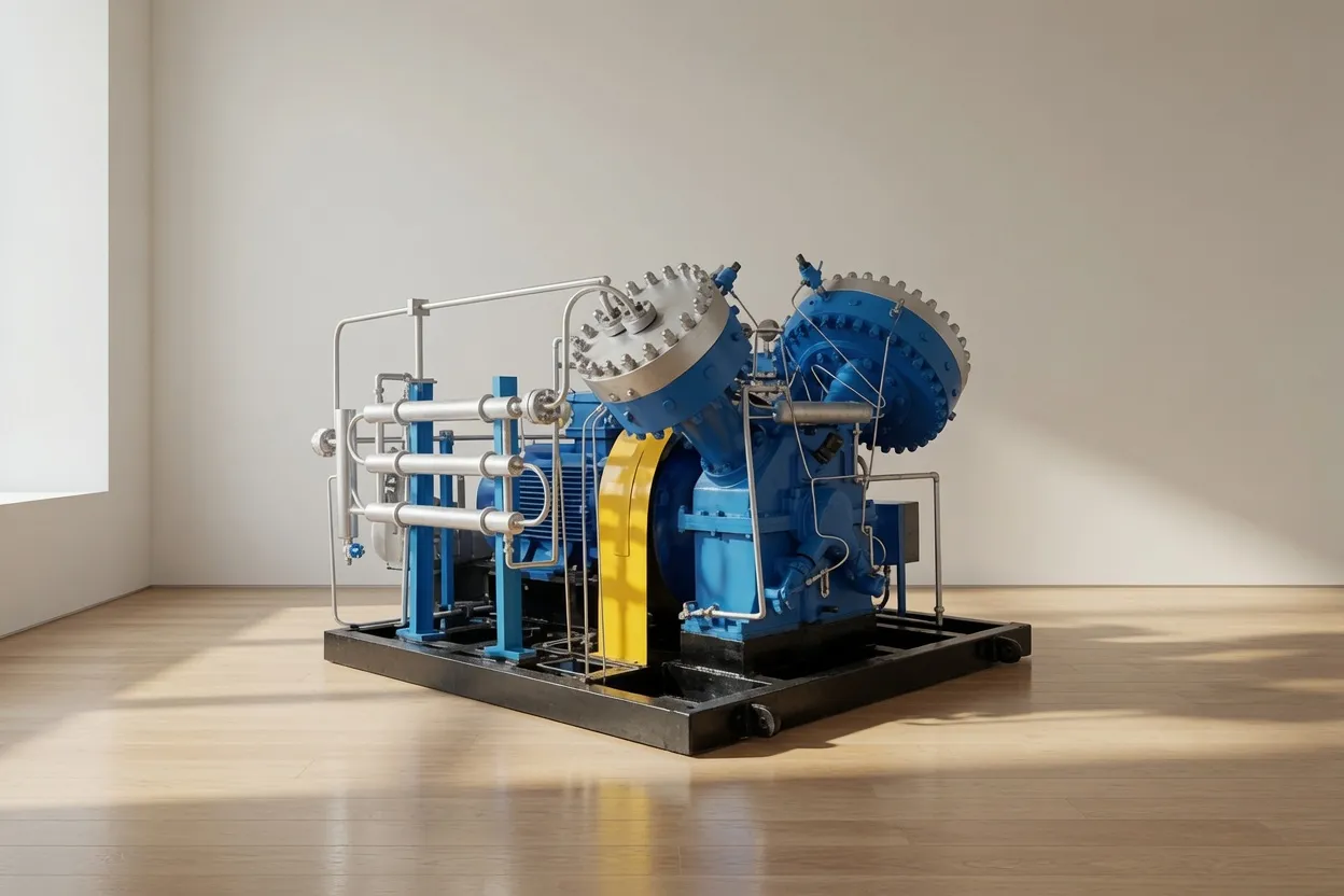
CM242GPV Medium-Pressure Oil-Free Screw Air Compressor
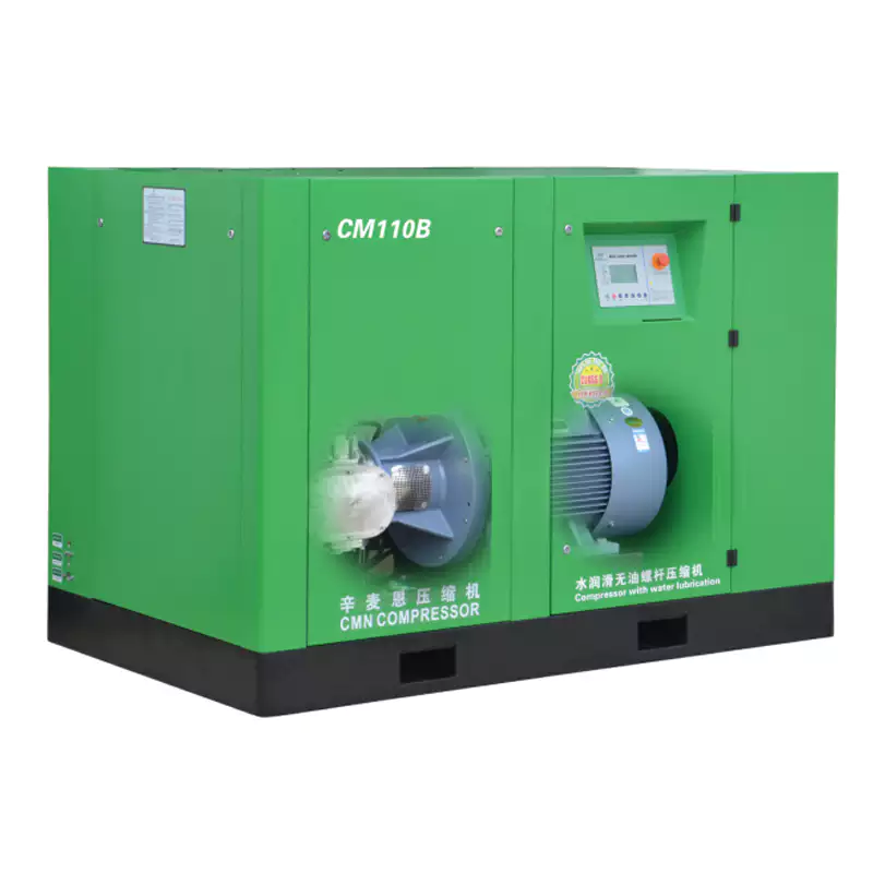
An ideal match for facilities needing continuous-duty, mid-range pressure output. This model covers the 125–250 PSI window most commonly identified in general manufacturing sizing exercises — making it a natural first recommendation after completing the 6-step sizing process above. Features built-in VSD capability, low noise design, and 100% oil-free delivery certified to meet stringent compressed air quality standards.
Frequently Asked Questions
Australia Oil Free Air Compressor Co., Ltd.
Charlton Industrial Area, Australia | [email protected]