Engineering Sizing Guide
The complete step-by-step methodology for correctly sizing an oil-free air compressor — calculating required flow (CFM/L/min), delivery pressure (PSI/MPa/bar), duty cycle, and receiver volume for industrial, pharmaceutical, food, dental, and laboratory applications.
Undersized compressors starve production lines of air at peak demand, triggering pressure drops that shut down pneumatic instruments, reduce cutting quality in laser machines, and — in regulated industries — potentially constitute a GMP deviation. Oversized compressors waste capital and energy, running at chronically low load factors that reduce efficiency and increase maintenance frequency through excessive cycling. Getting compressor sizing right is an engineering discipline with defined methods, not a rule-of-thumb exercise. This guide walks through every step of the correct sizing process for oil-free air compressors: how to calculate total demand in both metric and imperial units, how to determine the minimum delivery pressure, how duty cycle affects the apparent compressor size needed, how to size the receiver correctly, and how each application type — from dental to pharmaceutical to laser cutting — modifies the standard sizing approach. Whether you are specifying a new installation or auditing an existing system, the framework in this guide will give you the numbers you need to make the right choice.
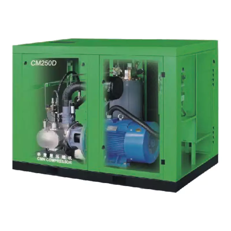
Oil-free screw compressor sizing — the correct approach combines peak flow demand, system pressure, duty cycle, and receiver volume calculations before selecting a specific model.
Understanding the Units: CFM, L/min, PSI, Bar, MPa
Before any sizing calculation, you need a firm grasp of the measurement units used for compressed air flow and pressure — both imperial (still widely used in Australian industry via US equipment datasheets) and metric (used in ISO standards, European and Asian equipment specifications, and all regulatory documentation).
Flow Rate Units
CFM — Cubic Feet per Minute
Imperial unit used on US-manufactured equipment datasheets. 1 CFM = 28.32 L/min. Most Australian buyers encounter CFM on American compressor and tool specifications.
L/min — Litres per Minute
Common metric unit in Australian and European specifications. Preferred for sizing calculations in SI units. 1 L/min = 0.0353 CFM.
m³/min — Cubic Metres per Minute
Used in large industrial specifications and ISO 1217 compressor datasheets. 1 m³/min = 1,000 L/min = 35.3 CFM.
⚠ FAD vs. Displacement
Always compare on FAD (Free Air Delivery) — the actual delivered volume at atmospheric reference conditions. Displacement (swept volume) is always higher and must not be used for sizing. ISO 1217 FAD is the correct benchmark.
Pressure Units
PSI — Pounds per Square Inch
Imperial pressure unit on US equipment. 1 PSI = 0.006895 MPa = 0.06895 bar. Common range: 100–175 PSI for industrial compressors.
bar — Bar
Widely used in European equipment. 1 bar = 0.1 MPa = 14.5 PSI. Most industrial compressors are rated at 7–10 bar.
MPa — Megapascal
SI unit used in ISO standards and Australian technical specifications. 1 MPa = 10 bar = 145 PSI. Standard industrial range: 0.7–0.9 MPa.
⚠ Gauge vs. Absolute
Equipment pressure ratings are gauge pressure (PSIG / barg / MPag) — above atmospheric. Absolute pressure = gauge + 0.1 MPa atmospheric. Use gauge throughout sizing calculations.
| PSI |
bar |
MPa |
Typical Application |
| 87 |
6 |
0.6 |
Dental instruments, light pneumatics |
| 102 |
7 |
0.7 |
Standard industrial, food production, lab |
| 116 |
8 |
0.8 |
Pharmaceutical, medical gas, standard compressor rating |
| 130 |
9 |
0.9 |
Higher-demand industrial, long distribution runs |
| 232 |
16 |
1.6 |
Laser cutting (thin-medium material), PET blowing |
| 435 |
30 |
3.0 |
Laser cutting (thick material), two-stage high pressure |
Step-by-Step Sizing Method
The correct sizing process follows four sequential steps. Each step builds on the previous one — skipping or approximating any step increases the risk of an incorrectly sized system.
1
Calculate Total Air Demand (FAD)
List every device, instrument, tool, and process that consumes compressed air. For each consumer, record its air consumption in L/min or CFM at its rated operating pressure. Sum all consumers that could be operating simultaneously — this is your peak simultaneous demand.
Then apply a diversity factor — in practice, not every tool runs at maximum consumption simultaneously. A diversity factor of 0.7–0.85 is typical for most industrial facilities; dental practices use 1.0 (all chairs may run simultaneously at peak); pharmaceutical manufacturing uses 0.9 (high utilisation). Multiply peak simultaneous demand × diversity factor = design demand (FAD required).
Worked Example
Consumer A: Packaging pneumatics — 120 L/min
Consumer B: Spray coating station — 80 L/min
Consumer C: Instrument air (4 points × 15 L/min) — 60 L/min
Consumer D: Conveyor actuators — 40 L/min
Peak simultaneous: 120+80+60+40 = 300 L/min
× Diversity factor 0.80: 300 × 0.80 = 240 L/min design demand
2
Determine Minimum Delivery Pressure
Identify the consumer with the highest minimum operating pressure in your system. This sets your minimum working pressure at the point of use. Add the pressure drop across your distribution system (pipework friction, fittings, filters, dryer) to determine the minimum compressor delivery pressure.
Typical system pressure drops: Well-designed distribution pipework: 0.05–0.10 MPa. Refrigerant dryer: 0.02–0.04 MPa. Coalescing + fine filter set: 0.02–0.04 MPa (clean). Total typical drop: 0.07–0.15 MPa. Add this to your highest consumer’s required pressure to get the compressor minimum delivery pressure.
Worked Example
Highest consumer minimum pressure: 0.60 MPa (6 bar / 87 PSI)
Distribution system pressure drop: 0.10 MPa
Filter + dryer pressure drop: 0.06 MPa
Minimum compressor delivery pressure: 0.60 + 0.10 + 0.06 = 0.76 MPa → select 0.8 MPa rated compressor
3
Apply the Duty Cycle and Headroom Factor
Duty cycle describes what fraction of time the compressor will be actually compressing air. A VSD oil-free screw compressor can run at 100% continuous duty — matching its output to demand without cycling. A fixed-speed screw runs load/unload cycles. Correctly applying duty cycle prevents undersizing in peak demand scenarios.
The standard sizing rule: the compressor’s rated FAD should exceed the design demand by 15–20% headroom for growth, future equipment additions, and system leaks. In regulated industries (pharmaceutical, food), add an additional 10% buffer to account for validation testing airflow and N+1 redundancy planning.
Worked Example
Design demand (from Step 1): 240 L/min
+ 15% headroom factor: 240 × 1.15 = 276 L/min minimum FAD
For regulated food facility, add 10% regulatory buffer: 276 × 1.10 = 304 L/min target FAD
→ Select a compressor rated at ≥ 320 L/min FAD at 0.8 MPa (next standard model above 304)
4
Size the Receiver Volume
The receiver (storage tank) serves three functions: smoothing demand variations, providing a buffer during compressor changeover or short-term overload, and providing a condensate collection point. The standard formula for minimum receiver volume:
V (litres) = (FAD in L/min × T in minutes × P1) ÷ (P1 − P2)
Where: T = desired autonomy time in minutes (typically 0.5–1.0 min); P1 = compressor cut-out pressure (absolute, bar abs); P2 = compressor cut-in pressure (absolute, bar abs). For a simpler rule of thumb: receiver volume ≥ 6–10× the compressor FAD in litres. A 300 L/min compressor pairs well with a 180–300 L receiver as a minimum.
Worked Example
FAD = 320 L/min; T = 0.5 min; P1 = 9 bar abs (8 barg cut-out + 1); P2 = 8 bar abs (7 barg cut-in + 1)
V = (320 × 0.5 × 9) ÷ (9 − 8) = 1,440 ÷ 1 = 1,440 L → specify 200 L receiver minimum; 500 L preferred for regulated applications
Note: for VSD compressors, cycling is eliminated — receiver sizing is simpler; use 3–5× FAD in litres as the minimum.
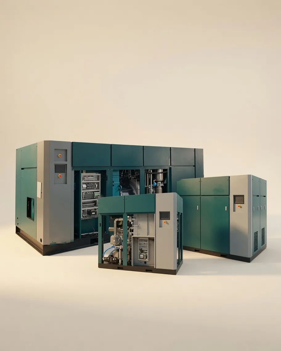
Correctly sized oil-free screw compressor installation — the system delivers consistent pressure at all consumption points with appropriate headroom for demand growth and maintenance events.
Application-Specific Sizing Rules
Each industry application type modifies the standard sizing approach with specific demand profiles, pressure requirements, and diversity factors. The following data covers the most common oil-free compressor applications in Australia.
Dental Practices
Dental air demand depends primarily on the handpiece type — turbine (air-driven) handpieces consume the most; electric handpieces use compressed air only for the 3-in-1 syringe and suction. Use a diversity factor of 1.0 for dental (all chairs may run simultaneously during busy periods).
| Chair Configuration |
L/min per Chair |
PSI Required |
Recommended Technology |
| Turbine handpiece + 3-in-1 |
60–80 |
55–75 PSI (0.38–0.52 MPa) |
Scroll (1–4 chairs), Duplex scroll (5–6 chairs) |
| Electric handpiece + 3-in-1 |
20–35 |
55–75 PSI |
Scroll or compact screw |
| Implant / surgical (per room) |
80–120 |
80–100 PSI (0.55–0.69 MPa) |
Dedicated screw or duplex scroll |
Pharmaceutical Manufacturing
Pharmaceutical air sizing requires calculating each manufacturing suite’s peak demand independently, then summing for the total plant supply. Apply a diversity factor of 0.85–0.95 (pharmaceutical batch operations tend toward high simultaneous utilisation). Add a minimum 15% GMP validation headroom. Use N+1 compressor configuration — size each unit to carry 100% load independently.
| Process |
Typical FAD (L/min) |
Min Delivery Pressure |
Air Class Required |
| Tablet coating pan (per pan) |
150–350 |
0.6–0.7 MPa |
Class B (ISO 1.2.0) |
| Fluid bed dryer (per unit) |
200–500 |
0.6–0.8 MPa |
Class B (ISO 1.2.0) |
| Sterile filling line purge |
50–150 |
0.3–0.5 MPa |
Class A (ISO 1.2.0) |
| Pneumatic actuators (per suite) |
100–300 |
0.5–0.7 MPa |
Class C (ISO 1.4.1) |
For a worked pharmaceutical example: a three-suite facility with 1 tablet coating pan + 1 fluid bed dryer + 1 filling line + actuators totals approximately 650–1,100 L/min peak demand. With 0.90 diversity and 15% GMP headroom: (900 × 0.90) × 1.15 ≈ 930 L/min FAD required → the CM132DV in N+1 duplex configuration is appropriate for this scale.
Laser Cutting
Laser cutting compressor sizing is dominated by required delivery pressure rather than flow rate in most installations. A single fibre laser cutting machine typically requires 800–2,000 L/min at 1.0–3.0 MPa (10–30 bar) depending on laser power and material thickness. The critical sizing rule: the compressor must maintain minimum nozzle pressure during maximum piercing demand — the highest instantaneous draw.
| Laser Power |
Material |
Required Pressure |
Flow (L/min) |
Recommended Model |
| 3–6 kW fibre |
Mild/SS <6mm |
1.6 MPa |
800–1,200 |
1.6MPa Oil-Free |
| 6–12 kW fibre |
SS/aluminium <12mm |
2.0–3.0 MPa |
1,200–2,000 |
3.0MPa 2-Stage |
| 12–20 kW fibre |
Thick plate >12mm |
3.0 MPa+ |
2,000–4,000 |
CM242GPV (consult) |
Food & Beverage Production
Food production compressor sizing uses a demand survey of all pneumatic actuators, conveyors, packaging machines, spray nozzles, and instrument air points. Apply a diversity factor of 0.75–0.85 for multi-line facilities. Add 20% headroom for BRCGS compliance buffer and future expansion. Minimum delivery pressure at the farthest point of use should be confirmed by a pipeline pressure-drop calculation — common oversight in under-pressured remote packaging lines.
The 6 Most Common Compressor Sizing Mistakes
MISTAKE 1
Using Displacement Instead of FAD
Compressor displacement (swept volume) is always larger than FAD — sometimes by 15–30%. Sizing on displacement leads to a compressor that cannot sustain system pressure at design demand.
MISTAKE 2
Ignoring Distribution Pressure Drop
Setting compressor delivery pressure equal to the highest consumer’s requirement without adding the system pressure drop. The result: consumers at the end of long distribution runs are starved of pressure during peak demand.
MISTAKE 3
No Growth Headroom
Sizing the compressor exactly to current demand with no headroom. As new equipment is added and leaks develop, the system runs at 95–100% load continuously — causing higher wear rates, higher energy costs, and eventual under-pressure events.
MISTAKE 4
Undersized Receiver
A too-small receiver causes fixed-speed compressors to cycle excessively — damaging motor windings and increasing energy consumption. With VSD, an undersized receiver reduces the VSD’s ability to respond to rapid demand changes.
MISTAKE 5
Not Accounting for System Leaks
An established facility with no active leak management programme loses 20–30% of compressed air through undetected leaks. Sizing without a leak allowance means the compressor will be fully loaded from day one with no room for new demand.
MISTAKE 6
Oversizing for Peak but Ignoring Average Load
Selecting a very large fixed-speed compressor to handle rare peak demand means the unit runs at 30–40% load most of the time — extremely energy inefficient. A properly sized VSD unit handles peak demand efficiently and reduces energy consumption at average loads.
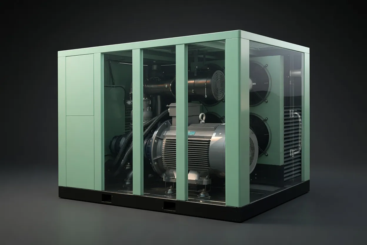
CM22G Series oil-free screw compressor — sized to deliver consistent 0.8 MPa supply across multiple simultaneous consumers with 15% growth headroom and VSD efficiency at partial load.
Recommended for Variable-Demand Facilities
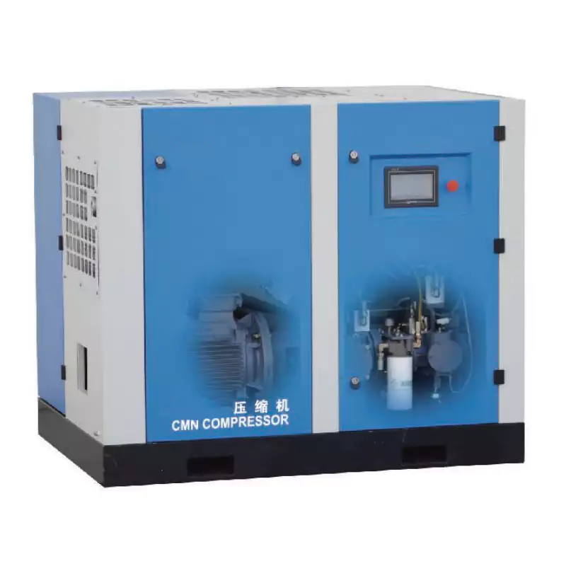
CM132DV VSD Water-Lubricated Oil-Free Compressor
For facilities with variable air demand — pharmaceutical batch operations, food production with shift-based scheduling, multi-use laboratories — the CM132DV’s VSD adjusts output in real time to match demand. Eliminates the energy waste of fixed-speed on-load/off-load cycling. ISO 8573-1 Class 0 certified. Our team provides free site-specific sizing calculations and energy cost estimates.
View Product & Request Free Sizing →
Frequently Asked Questions
How do I find the air consumption of my existing equipment to start a sizing calculation?
+
Three sources in order of preference: (1) Equipment manufacturer datasheet — most pneumatic tools and instruments specify air consumption in CFM or L/min at a rated pressure; look for “air consumption,” “air requirement,” or “FAD.” (2) Measured consumption — use a flow meter temporarily installed in the supply line to each major consumer; this is the most accurate method and eliminates guesswork. (3) Industry reference tables — published air consumption guides cover standard tool types (impact wrenches, spray guns, dental chairs, HPLC instruments) with typical ranges. If you have multiple tools of the same type, measure one and multiply by quantity. Note that tools are rarely all running at maximum consumption simultaneously — this is where the diversity factor applies.
My compressor is running at 95% load constantly. Am I undersized?
+
Not necessarily — but probably. First, check whether system pressure is being maintained at all demand points. If pressure is consistently at or near setpoint, the compressor is coping — but with no headroom for demand spikes, equipment additions, or increased system leaks. Second, perform an overnight pressure decay test (pressurise the system, shut the compressor off, measure pressure loss over 8 hours) to quantify the leak rate. A system losing more than 10% of working pressure overnight has significant leaks that are consuming compressor capacity. Third, review whether any new equipment has been added since the original sizing. If all these checks confirm genuine 95% load on design demand with no leaks, you are at capacity and should plan to add a second compressor unit — do not wait until the compressor is at 100% load and cannot maintain pressure.
What is the correct duty cycle for a VSD oil-free screw compressor?
+
VSD (variable speed drive) oil-free screw compressors are rated for 100% continuous duty — the motor speed simply slows down to match demand rather than switching off and on. There is no duty cycle restriction in the way there is for standard oil-free piston compressors (which are typically rated for 50–70% duty cycle). The practical lower speed limit of a VSD compressor is typically 30–40% of rated speed — below this, the compressor turns off and restarts when pressure drops. If your VSD compressor is frequently reaching its minimum speed and switching off and on, the compressor is oversized for the current demand — not a damage concern, but an energy efficiency suboptimum that can be addressed by adding a larger receiver to extend the off-cycle.
How does altitude affect compressor sizing?
+
Altitude reduces atmospheric pressure, which reduces the density of inlet air and therefore reduces the mass flow rate (and FAD) that a compressor delivers for a given swept volume. At 1,000 m above sea level (relevant for facilities in parts of NSW, Victoria, and Queensland), atmospheric pressure is approximately 89.9 kPa versus 101.3 kPa at sea level — a reduction of about 11%. A compressor rated at 500 L/min FAD at sea level will deliver approximately 445 L/min FAD at 1,000 m elevation. For high-altitude facilities, apply an altitude correction factor to the compressor’s rated FAD before confirming the sizing. Most compressor manufacturers publish altitude de-rating tables — request the corrected FAD at your site elevation when requesting quotations.
Should I size for peak demand or average demand?
+
Always size the compressor FAD for peak simultaneous demand (with appropriate diversity factor and headroom), not average demand. Average demand determines the energy cost and the appropriate VSD range, but the compressor must be capable of supplying peak demand without pressure dropping below the minimum operating point of any consumer. The receiver provides the buffer between average compressor output and instantaneous peak demand — a correctly sized receiver can absorb demand spikes of 150–200% of compressor FAD for short periods (30–90 seconds) before system pressure drops noticeably. This is why receiver sizing is equally important as compressor sizing — an undersized receiver forces the compressor to respond to every instantaneous demand spike rather than riding through them.
Get a Free Compressor Sizing Calculation
Australia Oil Free Air Compressor Co., Ltd. provides free site-specific compressor sizing calculations — tell us your application, consumers, and operating schedule, and we’ll provide the correct model, receiver size, and estimated annual energy cost.
Request Free Sizing Calculation
Email: [email protected] | Contact Us | About Us