
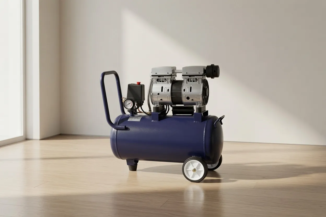
What Is Duty Cycle on an Air Compressor?
Duty cycle is the ratio of running time to total time within a defined cycle window, expressed as a percentage. For an oil-free air compressor, it represents the fraction of any given period during which the machine can operate at full load without thermal or mechanical damage. A compressor rated at 60% duty cycle can run for 6 minutes out of every 10, and must rest for the remaining 4 minutes to dissipate heat and allow component temperatures to stabilise.
This parameter originates from the thermal limitations of the compression element and motor. Every compression stroke generates heat. In oil-lubricated compressors, oil absorbs and carries that heat away. In oil free compressor designs — which rely on Teflon coatings, water injection, or precision dry-running clearances rather than oil — thermal management is more demanding, and the duty cycle rating reflects that engineering constraint directly.
Example: 6 min run ÷ 10 min cycle × 100 = 60% duty cycle
Required rest time = Total cycle − Run time = 10 − 6 = 4 min
What makes duty cycle particularly critical for oil-free compressors is the absence of a lubricating oil film between moving parts. PTFE (Teflon) ring coatings on piston compressors and precision-ground rotor clearances on dry-running screw compressors are both sensitive to sustained elevated temperatures. Exceeding the rated duty cycle accelerates coating degradation, often invisibly, until a sudden increase in oil carryover or loss of pressure signals a problem that has been building for months.
Duty Cycle Ratings by Oil-Free Compressor Type
Different compressor technologies carry fundamentally different duty cycle capabilities — a direct result of their compression mechanism, heat generation characteristics, and cooling design. Understanding these differences is essential before matching a compressor to any application.
What Actually Happens When You Exceed the Duty Cycle
Exceeding a compressor’s rated duty cycle is not immediately catastrophic — it is cumulative. The machine will typically continue running for some time. The damage accumulates in the background until one of several failure modes presents. Understanding these failure modes explains why duty cycle compliance is an operational discipline, not just a specification note.
How to Calculate Your Application’s Actual Duty Cycle
Many operators assume their application’s duty cycle based on observation — “we run the compressor about half the time.” This is unreliable. The actual operating duty cycle should be measured from controller data or calculated from known process parameters. Here is the structured approach:
Step 1 — Measure or Estimate Average CFM Demand
Identify the average CFM drawn during a representative production hour. This differs from peak demand and from the rated tool CFM sum — it is the time-weighted average across the full operating window. For a facility running at 80 CFM for 45 minutes and 20 CFM for 15 minutes of each hour, the weighted average is (80×45 + 20×15) ÷ 60 = 65 CFM average demand.
Step 2 — Compare to Compressor Rated Output
Divide average demand by the compressor’s rated FAD output. If your average demand is 65 CFM and your compressor is rated at 100 CFM, the load factor is 65%. For a fixed-speed machine, this load factor approximates the duty cycle — the compressor runs at 65% of available time to satisfy demand, then unloads.
Example: 65 CFM ÷ 100 CFM = 0.65 → 65% duty cycle
65% < 60% rated? No — this EXCEEDS the 60% duty limit of a piston compressor.
This is a commonly overlooked sizing error: the compressor output (100 CFM) easily covers peak demand (80 CFM), so the buyer assumes the machine is oversized and safe. But the average load factor of 65% exceeds a 60%-rated piston machine’s duty limit. The fix is either a compressor with a larger FAD rating (to reduce the load factor) or switching to a 100%-duty rotary screw design.
The Duty Cycle Safety Rule
Target: Actual Load Factor ≤ 80% of Rated Duty Cycle
For a 60%-rated piston compressor, the actual duty cycle should not exceed 48% (0.80 × 60%). This 20% headroom accounts for demand spikes, seasonal load variation, and gradual performance degradation over the service life. Sizing to the absolute rated limit leaves zero margin for operational variation.
Duty Cycle & Energy Efficiency: The Hidden Connection
Duty cycle has a direct and significant impact on air compressor efficiency. A fixed-speed compressor that runs at 50% duty cycle consumes energy while running, then consumes a smaller but non-negligible amount while unloaded (typically 15–25% of full-load power in load/unload control). The more time the machine spends cycling between loaded and unloaded states, the more energy is consumed per unit of useful air delivered.
This is one of the strongest economic arguments for a variable speed drive compressor in applications with variable demand. Instead of cycling on and off (each start consuming a current surge), a VSD machine ramps speed up and down — consuming power proportional to demand continuously, without the energy spikes of frequent load/unload transitions.
| Control Strategy | Energy at 50% Load | Cycling Losses | Best For |
|---|---|---|---|
| Fixed Speed — On/Off | 50% of rated kW | High (frequent starts) | Very small units only |
| Fixed Speed — Load/Unload | 60–70% of rated kW | Moderate | Stable baseload >70% duty |
| VSD Modulating | ~50% of rated kW | Minimal | Variable demand; 30–70% load range |
| Fixed Speed — Continuous (Screw) | 100% (always full load) | None | Constant 100% demand applications |
For oil-free piston compressors operating at high duty cycles (approaching 60%), frequent thermal cycling also has a maintenance cost: more heat cycles mean more thermal expansion/contraction cycles on valve plates and cylinder heads, shortening gasket and valve life compared to a machine that runs at a steadier, lower duty fraction.
Matching Duty Cycle to Your Application: A Decision Framework
Use this framework to determine which compressor technology suits your operating pattern, based on the expected duty cycle your application will impose:
Examples: Dental chair, tyre inflation, occasional spray painting, small lab instruments
Sizing note: Ensure actual load factor remains under 80% of the rated duty cycle with headroom for demand spikes
Examples: Medical clinics, electronics assembly, cleanroom instruments, food-grade packaging
Sizing note: The scroll’s 70–80% rating provides a comfortable margin at this demand level
Examples: Multi-shift manufacturing, food processing with batch peaks, laser cutting with idle periods
Sizing note: VSD delivers 100% duty at lower average energy cost than fixed-speed
Examples: 24/7 pharmaceutical production, continuous food processing, large-scale laser cutting
Sizing note: Fixed-speed at continuous load is more energy-efficient than VSD at >90% load
Using a Receiver Tank to Manage Duty Cycle on Piston Compressors
A correctly sized receiver tank is the most cost-effective tool for reducing the effective duty cycle on a piston or scroll compressor. By storing compressed air in the receiver during periods of low demand, the compressor can satisfy a burst demand spike from stored air rather than running continuously — effectively reducing the time-average duty cycle below the instantaneous peak demand would require.
The relationship is straightforward: a larger receiver extends the time between compressor on-cycles, reducing how often the machine runs and therefore lowering the duty cycle fraction. For piston compressors where duty cycle is the primary life-limiting factor, investing in a receiver tank significantly larger than the minimum calculation suggests often delivers better long-term economics than purchasing a more expensive continuous-duty machine.
V = receiver volume · P_high/P_low = pressure band (psia) · C = demand CFM
Larger V → longer cycles → lower duty fraction → longer compressor life
As a practical example: a 50 CFM demand with a 100-gallon receiver cycling between 115 and 100 PSI will have a calculated off-time of approximately 3.4 minutes per cycle. Doubling the receiver to 200 gallons extends that off-time to 6.8 minutes — cutting the compressor’s on-cycles per hour almost in half and meaningfully reducing cumulative thermal stress on PTFE rings and valves over the machine’s operating life.
Australia Oil Free Air Compressor: Duty Cycle Guidance You Can Trust
At Australia Oil Free Air Compressor Co., Ltd., every compressor recommendation we make includes a duty cycle assessment for your specific operating pattern. We do not recommend piston or scroll technology for applications where average load factors suggest sustained operation near rated duty limits — not because those products are inferior, but because matching the right technology to the actual thermal demand is the foundation of reliable, low-maintenance operation.
Our oil-free rotary screw compressor range is purpose-built for continuous-duty industrial environments. For applications where intermittent-use piston or scroll units are appropriate, we specify units with verified duty ratings and recommend receiver sizing that keeps actual duty fractions within safe operating margins. Every recommendation is backed by our engineering team’s analysis — not a catalogue lookup.
Email us at [email protected] with your production schedule and tool list — we will confirm the right technology and duty cycle margin for your application.
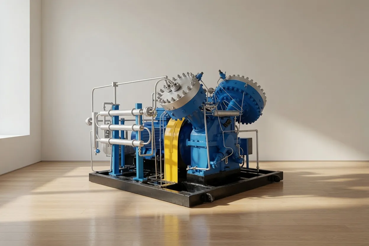
CM45D Low-Pressure Oil-Free Screw Compressor (Water Lubrication)
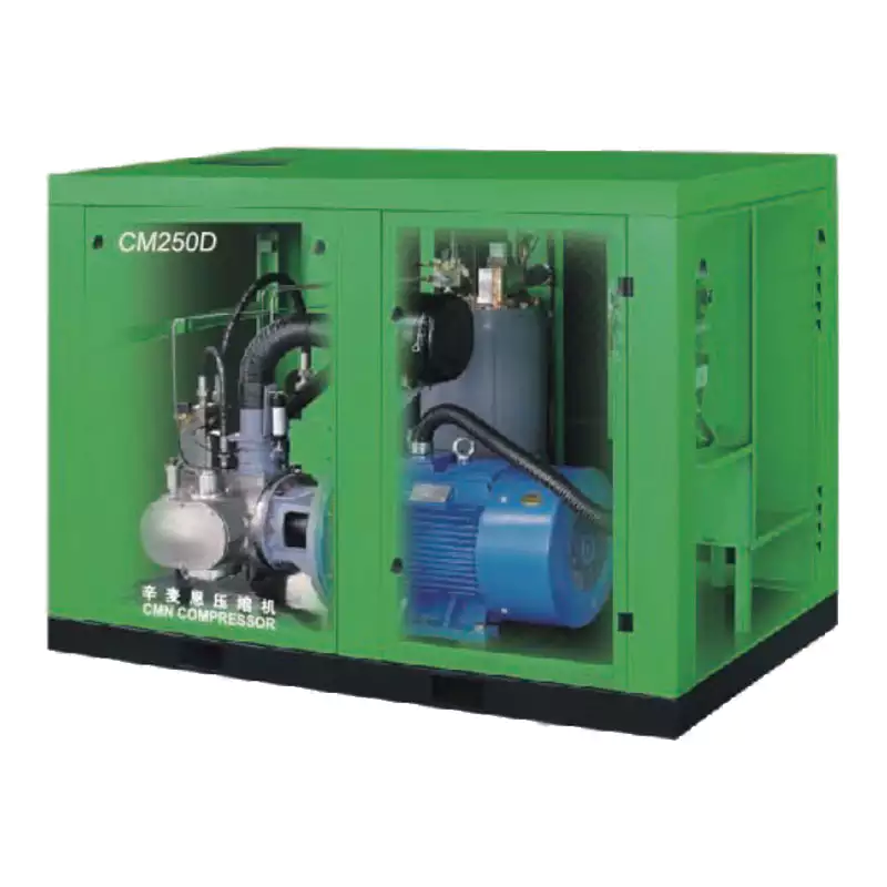
The CM45D is the defining answer to duty cycle concerns in industrial and process environments. As a water-lubricated oil-free rotary screw compressor, it operates at 100% continuous duty with no mandated rest intervals — eliminating the operational constraints that burden piston and scroll designs. Water lubrication provides natural thermal regulation across the full load range, keeping discharge temperatures stable even in demanding conditions. For any facility where a duty cycle conversation keeps coming up, the CM45D removes it from the agenda entirely.
Frequently Asked Questions
Australia Oil Free Air Compressor Co., Ltd.
Charlton Industrial Area, Australia | [email protected]