
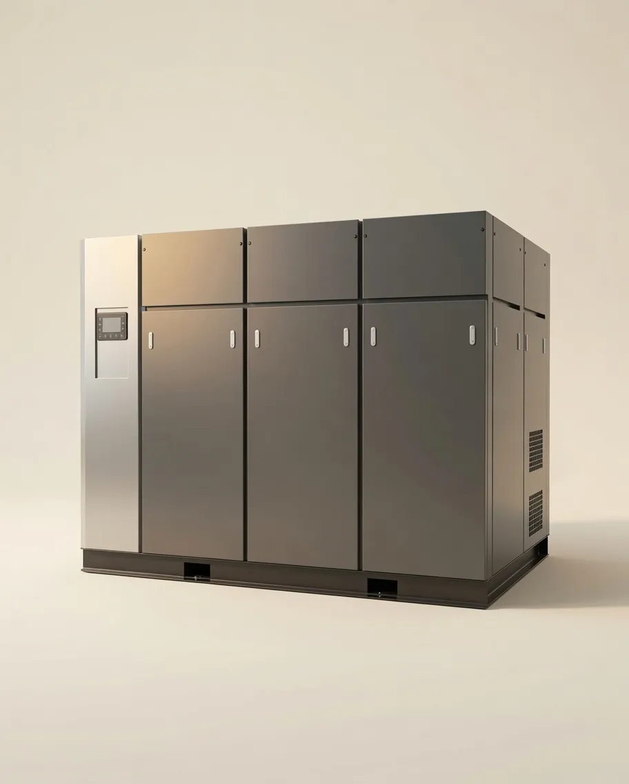
The Challenge of Multi-Tool Compressed Air Systems
Running a single oil-free air compressor to supply multiple tools across a workshop, production line, or facility is the standard setup in virtually every industrial and trade environment. It is also the most common source of compressed air sizing errors — because most buyers add up all their tools’ CFM ratings and buy a compressor to match, without accounting for the critical variables that make this simple sum wildly inaccurate.
The total CFM rating of all tools in a facility is almost never the right figure to size from. If a workshop has 15 tools with a combined CFM rating of 150, but only 6 of them ever run at the same time and none of them runs at 100% duty cycle for the entire shift, the actual peak simultaneous demand might be 45–60 CFM — a third of the naive total. Buy a 150 CFM compressor and you have invested significantly more capital than needed for a machine that runs at 30% load most of the day. Buy a 60 CFM compressor correctly matched to real demand, and the system performs flawlessly.
The good news is that the methodology for getting this right is straightforward — it just requires a disciplined approach to data collection and a few key calculations covered in detail below.
Understanding the Three Types of Demand in a Multi-Tool System
Before calculating, it helps to understand that compressed air demand in a multi-tool environment exists at three different levels simultaneously. Sizing for the wrong level — or failing to account for all three — is where most errors occur.
Most industrial compressor sizing should target peak simultaneous demand as the primary specification driver — not average demand (which leads to undersizing) and not installed total demand (which leads to oversizing). Burst demand is handled by receiver tank volume, not compressor output rating.
Simultaneity Factors by Industry & Tool Count
The simultaneity factor — the fraction of installed tools likely to be running at the same moment — varies significantly with industry type, workforce size, and production pattern. Using an incorrect simultaneity factor is as consequential as miscounting your tools. The table below provides industry-validated factors based on field data from compressed air system audits:
| Environment / Industry | Tool Count | Simultaneity Factor | Notes |
|---|---|---|---|
| Trade & Workshop | |||
| Automotive workshop | 2–5 | 0.90–1.00 | Small team; tools often run together |
| Automotive workshop | 6–12 | 0.75–0.85 | Bays work somewhat independently |
| Fabrication / welding shop | 4–10 | 0.65–0.75 | Grinding/cutting cycles don’t fully overlap |
| Manufacturing | |||
| Assembly line (timed cycles) | 10–30 | 0.80–0.95 | Synchronised cycle → higher simultaneity |
| General manufacturing floor | 15–50 | 0.65–0.75 | Standard industrial benchmark |
| Large automated plant | 50+ | 0.50–0.65 | Statistical diversity reduces peak |
| Specialised | |||
| Dental / medical facility | 2–8 chairs | 0.60–0.75 | Appointment scheduling reduces overlap |
| Food processing (pneumatic conveyors) | Continuous | 0.85–1.00 | Production line; most actuators running together |
| Spray painting booth (multiple guns) | 2–6 guns | 0.70–0.85 | Painters have overlapping schedules |
If your production process has synchronised cycles — such as an assembly line where all stations activate pneumatic tools at the same moment — use a higher simultaneity factor (0.85–1.00) regardless of tool count. Simultaneous activation from a PLC or timing signal overrides the statistical diversity that makes lower factors valid for independent manual operations.
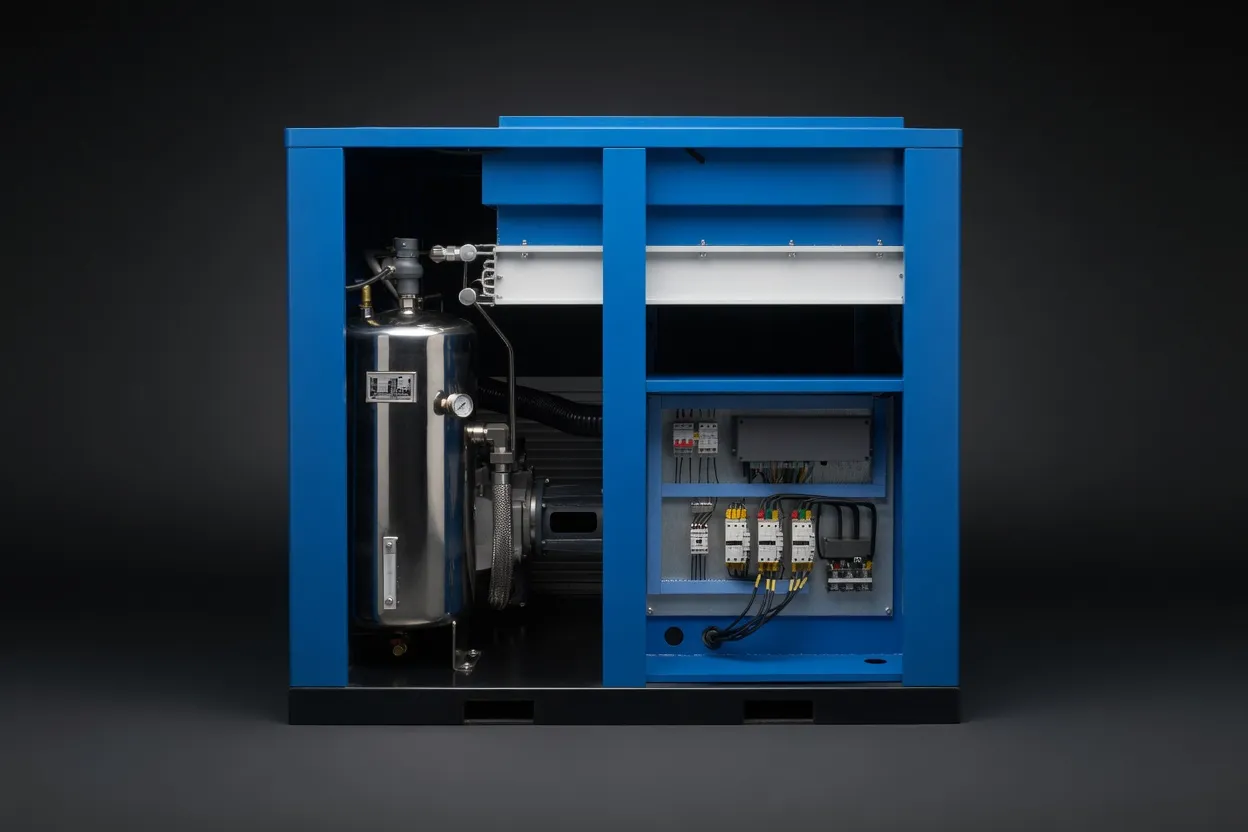
Step-by-Step: Calculating CFM for a Multi-Tool System
Follow this structured calculation process to arrive at a defensible, accurate CFM specification for any multi-tool installation. Every step matters — each one addresses a real-world variable that the previous step omits.
Worked Example: Metal Fabrication Workshop
A 6-employee metal fabrication workshop in Perth operates the following tools during the busiest shift. No desiccant dryer is used; a refrigerated dryer handles moisture control. The piping was installed 5 years ago and has not been leak-tested.
| Tool | Qty | Rated CFM | Individual Duty | Effective CFM |
|---|---|---|---|---|
| Angle grinders | 4 | 6.5 | 65% | 16.9 |
| Impact wrenches (3/4″) | 2 | 8.5 | 35% | 5.9 |
| Plasma cutter | 1 | 6.0 | 75% | 4.5 |
| Air drill | 2 | 4.0 | 50% | 4.0 |
| Blow guns | 4 | 3.0 | 20% | 2.4 |
| Sum of effective CFM (all tools) | 33.7 CFM | |||
Step 2 — × Simultaneity (0.70, fab shop 6-tool): × 0.70 → 23.6 CFM
Step 3 — + Leakage (20%, older piping): + 4.7 → 28.3 CFM
Step 4 — × Growth factor (1.20): × 1.20 → 33.9 CFM
→ Required FAD: 35 CFM at 100 PSI
An oilless air compressor rated at 35–40 CFM FAD at 100 PSI would be the correct specification. Given the fabrication environment and moderate sustained use pattern, a scroll or small rotary screw unit at 40 CFM with an 80–100 gallon receiver provides comfortable margin across the working day.
Managing Mixed-Pressure Tools from One Compressor
A common scenario in multi-tool environments is the coexistence of tools with very different air compressor PSI requirements on the same system. An automotive workshop may run impact wrenches at 90 PSI alongside a plasma cutter that needs 100 PSI and a sandblast cabinet requiring 110 PSI. A food processing facility might supply pneumatic conveyors at 90 PSI alongside a tablet press requiring 115 PSI and a compressed air-driven N₂ generator at 125 PSI.
The Zone Regulation Approach
The standard and most cost-effective approach for mixed-pressure multi-tool systems is zone regulation: set the compressor outlet to the highest-pressure zone requirement plus line loss allowance, then use point-of-use or zone pressure regulators to reduce supply to each lower-pressure zone. This is typically more economical than running multiple separate compressors for facilities with total demand under 500 CFM.
- → Pressure zones differ by less than 60 PSI
- → High-pressure zone CFM demand is less than 40% of total
- → Total system demand is under 400–500 CFM
- → Capital budget favours one compressor over two
- → High-pressure zone requires 200+ PSI (laser cutting)
- → Low and high pressure zones have very different air quality needs
- → High-pressure demand is continuous and large volume
- → N+1 redundancy is required for production continuity
When high-pressure demands such as laser cutting (175–450 PSI) coexist with general facility air (90–115 PSI), a two-compressor approach is nearly always more energy-efficient. Running a high-pressure compressor down to 90 PSI through a regulator wastes the energy spent compressing to 200+ PSI. A dedicated medium-pressure unit for laser cutting and a standard unit for general facility air avoids this waste, and the two-machine redundancy is a valuable operational benefit for production-critical facilities.
Distribution Pipework: The Overlooked Variable in Multi-Tool Systems
In multi-tool systems, the distribution pipework is often the weakest link — not the compressor. A correctly sized compressor delivering the right CFM at the outlet can still fail to provide adequate pressure at every tool if the pipework is undersized, poorly routed, or fitted with excessive restrictions.
The key principle for multi-tool distribution is to size the main header pipe for the total simultaneous demand, then branch at appropriate points with individual runs sized for each zone’s demand. Using a ring main (loop) rather than a radial main provides more even pressure distribution across all connection points — particularly valuable in facilities where tools at the far end of a radial run have historically experienced lower pressure than those near the compressor.
| Pipe Diameter | Max CFM at 100 PSI (low loss) | Pressure Drop per 100 ft at Max Flow | Typical Application |
|---|---|---|---|
| ½” (12mm) | 15–20 CFM | 3–5 PSI | Single tool drops, short runs (<10m) |
| ¾” (20mm) | 35–50 CFM | 2–4 PSI | Small workshop main, 2–4 tool branches |
| 1″ (25mm) | 80–100 CFM | 1.5–3 PSI | Medium facility main header, up to 10 tools |
| 1¼” (32mm) | 130–160 CFM | 1–2 PSI | Large workshop main, production line header |
| 2″ (50mm) | 300–400 CFM | <1 PSI | Industrial plant ring main, multi-zone header |
The data above makes the cost of undersized pipework visible: a ½” pipe at 50 CFM demand will drop 8–12 PSI per 100 feet — enough to leave tools at the end of a 30-metre run operating 5–8 PSI below the system setpoint. This is why tools at the “end of the line” often underperform in workshop settings even when the compressor is correctly sized.
Complete Multi-Tool System Design from Australia Oil Free Air Compressor
Our engineering team at Australia Oil Free Air Compressor Co., Ltd. handles multi-tool system sizing as a complete exercise — from demand inventory through pipe sizing to compressor and receiver specification. We have supported workshops, manufacturers, medical facilities, and food processing plants in correctly sizing systems that run reliably for years without the short-cycling, pressure sag, and equipment wear that come from improper sizing.
Whether you are building a new facility, expanding an existing system, or troubleshooting a compressor that keeps tripping or delivering inconsistent pressure, our team can review your tool inventory, apply correct simultaneity and leakage factors, and recommend the right oil-free compressed air system configuration — including pipe sizing guidance at no extra charge.
Email your tool list and facility description to [email protected] or visit our About Us page to learn more about our approach.
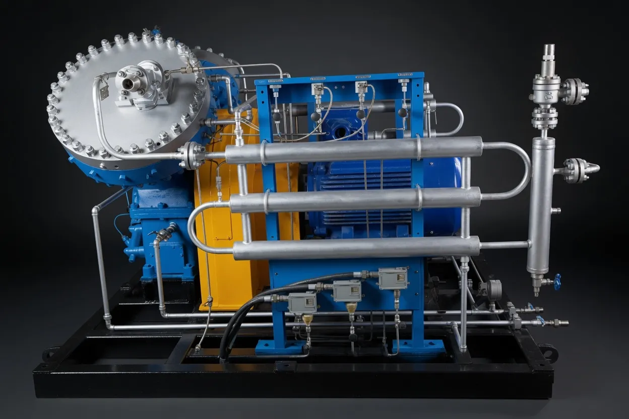
Screw Air Compressor for Laser Cutting — 1.8 MPa Micro-Oil
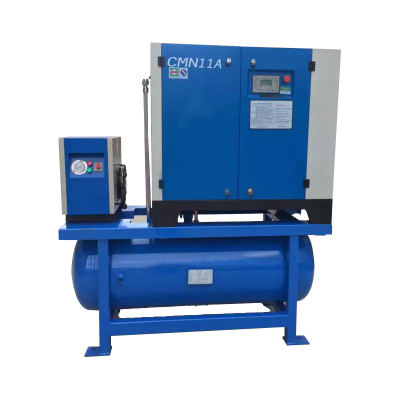
For multi-tool facilities where laser cutting is the highest-pressure application, this 1.8 MPa (261 PSI) micro-oil screw compressor provides the dedicated high-pressure supply that the cutting process demands — while allowing the rest of the facility to run from a standard-pressure oil-free unit via zone regulation. This two-compressor strategy is the approach we recommend for most mixed facilities running fibre laser cutting alongside general pneumatic tools, delivering both the pressure precision the laser needs and the energy efficiency the general system benefits from.
Frequently Asked Questions
Australia Oil Free Air Compressor Co., Ltd.
Charlton Industrial Area, Australia | [email protected]