
What Is a Two-Stage Air Compressor?
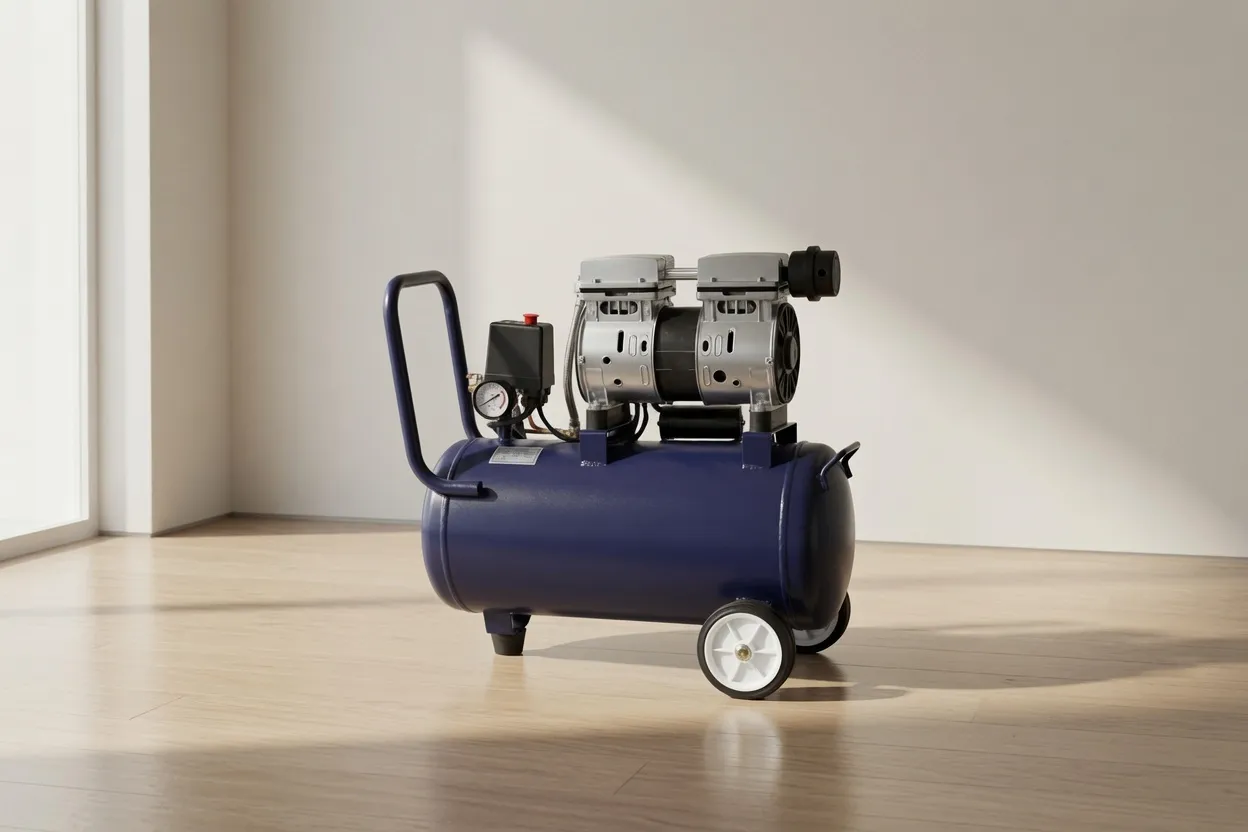
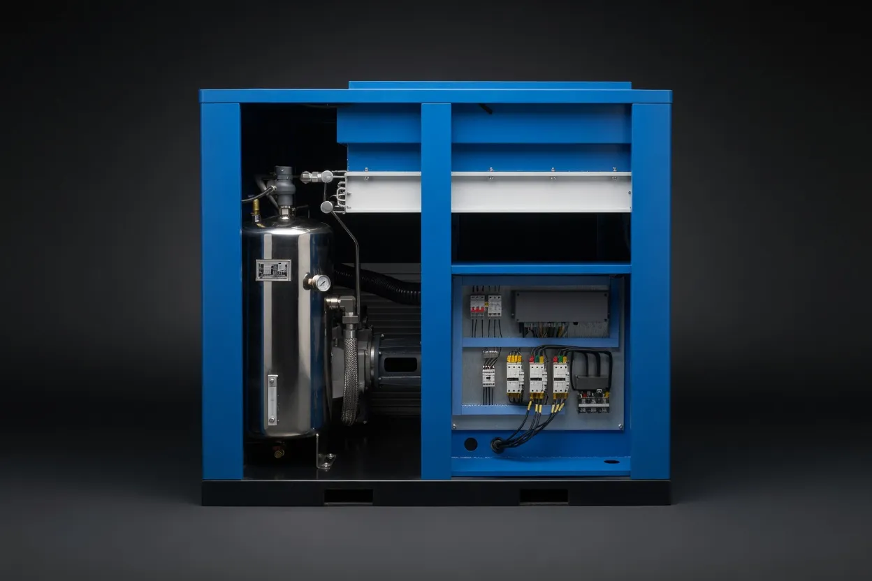
A two stage air compressor compresses air in two sequential steps, with an intercooler between them. In the first stage, air is drawn from atmosphere and compressed to an intermediate pressure — typically 50–100% of the final target pressure. This partially compressed air then passes through an intercooler, where heat from the first compression stage is removed. The cooled air enters a second compression stage, where it is compressed to the final discharge pressure.
This staged approach directly addresses one of the most important constraints in compression thermodynamics: temperature rise is exponential with pressure ratio. Compressing air from 14.7 psia (atmospheric) to 147 psia (10 bar) in a single step generates discharge temperatures of 280–350°C. Splitting the same compression into two stages with intercooling holds discharge temperatures below 160–200°C per stage — and the intercooling energy removal allows the second stage to start with cooler, denser air, significantly reducing the work required to reach the final pressure.
For oil-free air compressors, this temperature advantage is even more significant. Oil-free compression elements — PTFE-coated pistons, dry-running screw rotors, or water-injected rotors — all have maximum temperature limits that constrain the pressure ratio achievable in a single stage. Two-stage design allows oil-free technology to reach pressures that would be thermally impossible for any single-stage oil-free design.
The Thermodynamic Advantage: Why Two Stages Are More Efficient
The efficiency benefit of two-stage compression is grounded in fundamental thermodynamics. Understanding it — even at a conceptual level — explains why engineers consistently specify two-stage designs above certain pressure thresholds, regardless of other factors.
Quantifying the Efficiency Gain
The theoretical power saving from two-stage compression with perfect intercooling (returning air to intake temperature between stages) is given by comparing isothermal and adiabatic work. In practice, real intercoolers achieve 80–95% of perfect cooling, but the efficiency gain is still substantial:
| Final Pressure | Single-Stage Power (relative) | Two-Stage Power (relative) | Efficiency Gain | Max Discharge Temp (single) |
|---|---|---|---|---|
| 100 PSI (7 bar) | 100 | 97 | 3% — marginal | 180°C |
| 145 PSI (10 bar) | 100 | 94 | 6% — noticeable | 230°C |
| 200 PSI (14 bar) | 100 | 90 | 10% — significant | 300°C (exceeds oil-free limits) |
| 290 PSI (20 bar) | 100 | 85 | 15% — substantial | 400°C+ (single-stage not viable) |
| 435 PSI (30 bar) | — (not viable single-stage) | 100 | Only option | Impossibly high |
The data above makes clear why two-stage becomes mandatory, not merely preferable, above approximately 175–200 PSI for oil-free designs. Single-stage oil-free compression above this pressure would push discharge temperatures above the operating limits of every known oil-free compression element material — not just a matter of efficiency, but a fundamental material constraint.
Single-Stage vs Two-Stage: Which Applies Where?
The pressure requirement is the primary determinant of stage count. Here is the practical guidance for oil-free applications across the full industrial pressure range:
Air Compressor Efficiency: How Two-Stage Changes the Numbers
Air compressor efficiency is typically expressed as specific power: kW consumed per 100 CFM of FAD delivered at operating pressure. This normalised metric allows meaningful comparison between compressors of different sizes. Two-stage designs improve specific power primarily through the intercooling effect — the second stage starts with air that is 100–150°C cooler than it would be in a single-stage discharge, meaning the compressor does less work to achieve the same final pressure.
The efficiency of intercooling itself depends on the intercooler design. Air-cooled intercoolers achieve 80–90% approach to ambient temperature; water-cooled intercoolers achieve 90–95%. The closer the intercooler outlet approaches ambient temperature, the greater the efficiency gain in the second stage. For two-stage oil-free oil-free rotary screw compressors operating at 200–300 PSI, the intercooler is not an optional accessory — it is the primary mechanism by which the machine achieves its rated efficiency.
In Australian sites with summer ambient temperatures regularly exceeding 35°C — common across Western Australia, Queensland, and the Northern Territory — water-cooled intercooling maintains consistent second-stage efficiency that air-cooled designs cannot match during peak summer conditions. This makes water-cooled two-stage designs particularly valuable for high-pressure applications in hot-climate locations.
Horsepower Sizing for Two-Stage Oil-Free Compressors
Estimating air compressor horsepower for a two-stage design requires accounting for both compression stages plus intercooler and aftercooler auxiliary loads. The simplified rule of thumb for single-stage (4–5 CFM/HP at 100 PSI) does not apply directly at the higher pressures where two-stage designs operate.
| Operating Pressure | CFM per HP (two-stage) | HP needed for 100 CFM | Typical Application |
|---|---|---|---|
| 145 PSI (10 bar) | 3.8–4.2 CFM/HP | 24–26 HP | Laser cutting (entry), high-pressure workshop |
| 200 PSI (14 bar) | 2.8–3.2 CFM/HP | 31–36 HP | Mid-power fibre laser, nitrogen generator feed |
| 250 PSI (17 bar) | 2.3–2.7 CFM/HP | 37–43 HP | High-power laser, composite moulding |
| 300 PSI (20 bar) | 1.9–2.2 CFM/HP | 45–53 HP | High-pressure N₂ assist, specialty forming |
| 435 PSI (30 bar) | 1.2–1.5 CFM/HP | 67–83 HP | PET bottle blowing pre-stage, SCBA filling |
These figures assume modern, well-maintained equipment with effective intercooling. Older designs, high ambient temperatures, or degraded intercoolers may deliver 10–20% less CFM per HP than these benchmarks suggest. Always request the manufacturer’s measured performance data at your specific operating pressure — not interpolated catalogue values — for large capital equipment decisions.
Two-Stage Oil-Free Compressor Applications: Industry by Industry
Combining Two-Stage Compression with VSD: The High-Efficiency Configuration
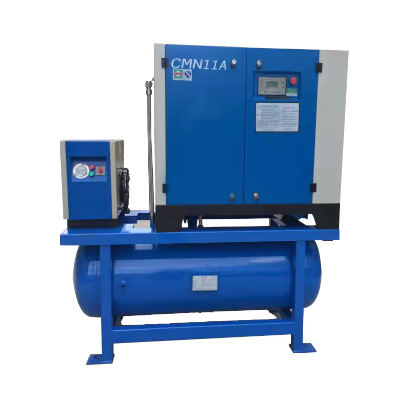
The most energy-efficient configuration available for variable-demand, high-pressure oil-free applications combines two-stage compression with a variable speed drive compressor motor. Each technology contributes a distinct efficiency mechanism: two-stage intercooling reduces the energy per unit of compression at high pressures; VSD modulation reduces the energy wasted when demand falls below maximum. Together, they achieve specific power figures that are 20–35% better than fixed-speed single-stage equivalents at the same pressure and similar flow.
This combination is particularly valuable for laser cutting facilities where output varies significantly — night shifts, weekends, and job changeovers all create periods of substantially reduced demand. A two-stage VSD oil-free screw compressor handles these transitions smoothly, maintaining exact pressure setpoint (±2 PSI) while ramping down speed to minimum, then recovering instantly when cutting recommences.
Any facility with operating pressure above 175 PSI AND significant demand variation (greater than 30% swing between peak and off-peak) should seriously evaluate a two-stage VSD oil-free unit. The combined capital premium over a single-stage fixed-speed unit is typically 30–50%, with payback periods of 2–4 years from combined energy savings. At 200+ PSI, the two-stage portion alone is thermally necessary — the VSD portion then adds incremental payback on top of what is already a mandatory design choice.
Australia Oil Free Air Compressor: High-Pressure Two-Stage Expertise
Two-stage oil-free compressor selection is more technically complex than standard-pressure units — pressure ratios, intercooler specification, motor sizing at altitude, and high-pressure distribution pipework all interact in ways that require engineering experience to navigate correctly. Our team at Australia Oil Free Air Compressor Co., Ltd. has delivered two-stage oil-free systems for laser cutting centres, PET bottle manufacturers, composite moulding facilities, and nitrogen generation applications across Australia.
Every two-stage proposal we provide includes the following as standard: measured FAD at specified operating pressure (not catalogue interpolation), intercooler sizing confirmation for your site’s ambient temperature range, two-stage pressure ratio optimisation (intermediate pressure selection for maximum efficiency), and downstream piping adequacy review for your working pressure. These factors are too consequential to leave to assumption on a high-pressure installation.
Contact us at [email protected] to discuss your high-pressure two-stage requirements.
Screw Air Compressor for Laser Cutting — 3.0 MPa Two-Stage Micro-Oil
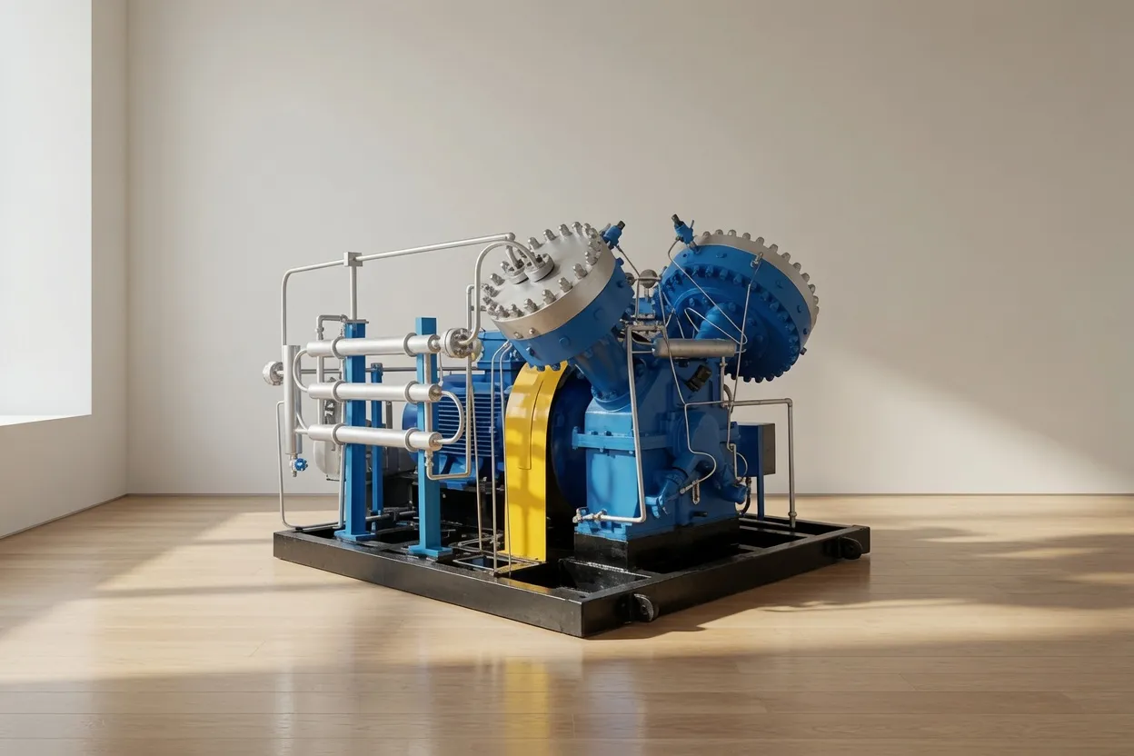
Our 3.0 MPa (435 PSI) two-stage screw compressor is engineered for the most demanding fibre laser cutting applications — where single-stage compression reaches its absolute thermal and mechanical limits. Two-stage compression with effective intercooling allows this unit to deliver stable, high-pressure assist gas with a specific power consumption 12–18% better than single-stage designs at the same pressure. For high-power laser cutting centres processing thick stainless steel, aluminium plate, and specialty alloys, this is the compressor that allows the laser to operate at its rated cutting parameters without pressure-related quality compromises.
Frequently Asked Questions
Australia Oil Free Air Compressor Co., Ltd.
Charlton Industrial Area, Australia | [email protected]